Magnetic recording medium and magnetic memory device for high density recording

Active Publication Date: 2006-03-16
WESTERN DIGITAL TECH INC
View PDF16 Cites 3 Cited by
  • Summary
  • Abstract
  • Description
  • Claims
  • Application Information

AI Technical Summary

Benefits of technology

[0010] The upper magnetic layer 72 shown in FIG. 3 of Patent document 4 has a composition of: Co-20 at. % Cr-12 at. % Pt-7 at. % B alloy, that is, the total for the concentrations of Co and Pt is 73%, and the total for the concentrations of Co and Pt in the lower magnetic layer 71 is from 77 to 82%. When the thickness of the lower magnetic layer 71 with the composition described above is increased, exchange coupling is increased in the lower magnetic layer which is remote from the head compared with the upper magnetic layer, to increase the medium noises.
[0011] The present invention intends to provide a longitudinal magnetic recording medium having a high medium S / N, with no problem in the overwrite characteristic, excellent in the bit error rate and sufficiently stable also in view of thermal fluctuation. Further, the invention intends to provide a magnetic memory device of high reliability capable of attaining an areal recording density of 95 Mbit or more per 1 mm2 by combination with a magnetic head of higher sensitivity.
[0019] As the first magnetic layer, a Co—Cr alloy, Co—Cr—B alloy, Co—Cr—Pt alloy, Co—Cr—Ta alloy, etc. can be used. Particularly, in a medium in which the first magnetic layer and the second magnetic layer are anti-ferromagnetically coupled, when a magnetic layer containing platinum in the first magnetic layer is used, the medium noises can be decreased and a medium capable of decreasing the thermal fluctuation and having high power resolution, as well as with high medium S / N can be obtained.
[0022] As the substrate, it is preferred to use a chemically strengthened glass substrate or a rigid substrate formed by plating a phosphorus-containing nickel alloy to an aluminum alloy. It is preferred to apply fine texturing on the substrate substantially in the circumferential direction of a disk in view of providing magnetic anisotropy. In the surface roughness as measured in the radial direction of the disk, when a substrate with a maximum height Rmax of from 2.68 nm to 4.2 nm, and an average surface roughness Ra of from 0.23 nm to 0.44 nm is used, there is no problem in view of flying reliability as a result of measuring the size of 5 μm square by an intermittent-contact atomic force microscope.
[0026] This invention can provide a longitudinal magnetic recording medium having a high medium S / N, with no problems in view of the overwrite characteristic, excellent in the bit error rate and sufficiently stable also to thermal fluctuations and further can provide a magnetic memory device of high reliability capable of attaining an areal recording density of 95 Mbits or more per 1 mm2 by combination with a magnetic head at higher sensitivity.

Problems solved by technology

Since excess refinement of the grain size and decrease of Brt result in the degradation of the thermal stability, decrease of noises is limited and higher coercivity of the medium has been considered together.
Although the half amplitude pulse width PW50 of the isolated read pulse output can be improved shorter by increasing the coercivity, this tends to result in determination of the overwrite characteristic and compatibility between the high coercivity and the overwrite characteristic is limited.
However, the combination of the techniques described above is still insufficient for attaining an areal recording density of 95 Mbits or more per 1 mm2 and it is necessary to further improve the read output and decrease the medium noises.
Since the lower magnetic layer having deviation for the lattice constant from that of the spacer layer includes disturbance of the crystallographic orientation, increase of the thickness for the lower magnetic layer causes increase of noises.

Method used


Image

  • Magnetic recording medium and magnetic memory device for high density recording
  • Magnetic recording medium and magnetic memory device for high density recording
  • Magnetic recording medium and magnetic memory device for high density recording

Examples


example 1

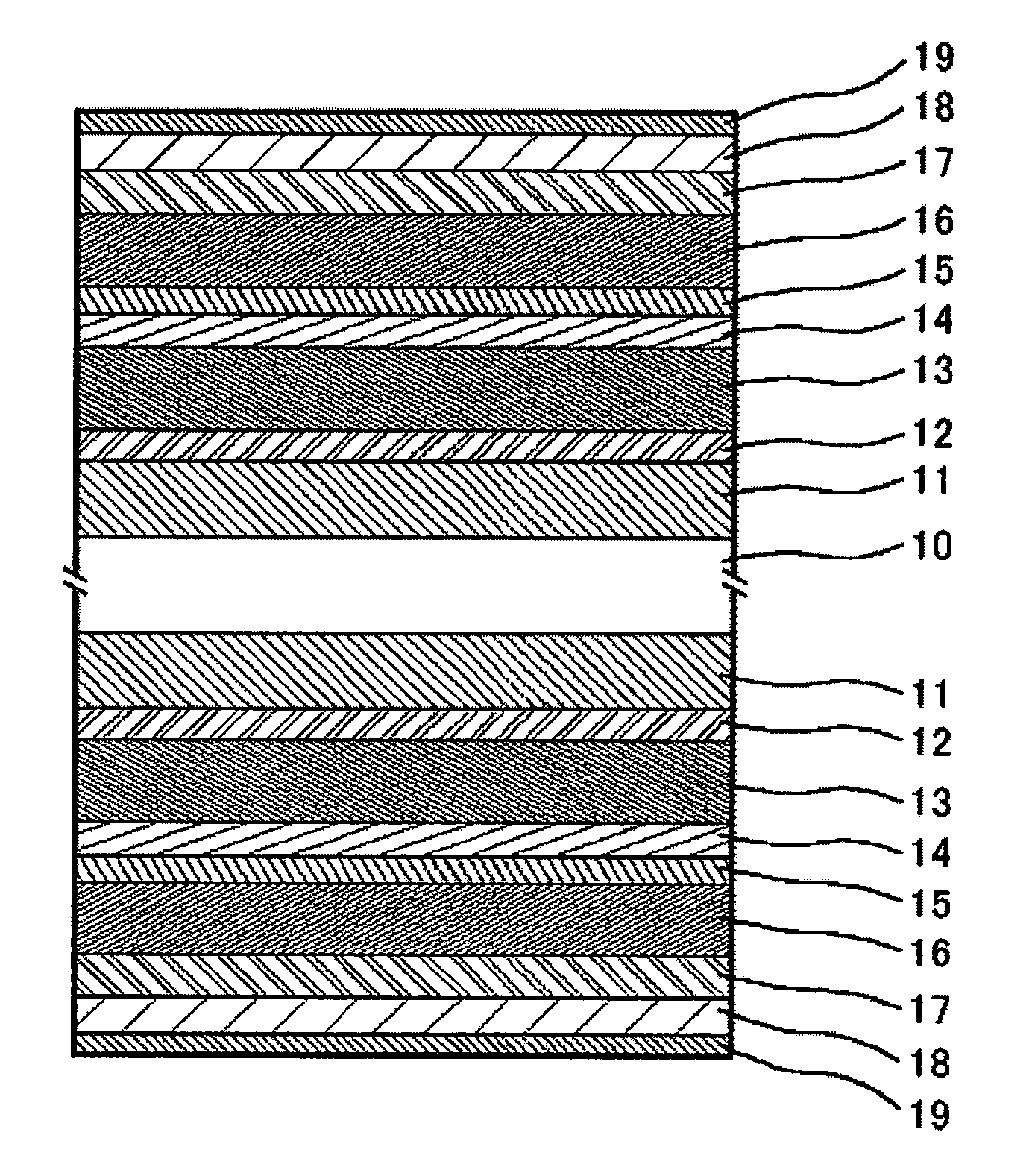
[0033]FIG. 1 shows a cross sectional structural view of a magnetic recording medium according to Example 1 of the invention. After alkali cleaning an alumino silicate glass substrate 10 chemically strengthened at the surface and drying the same, a Co—SO at. % Ti alloy of 15 nm thickness as a first underlayer 11, and a W-30 at. % Co alloy layer of 3 nm thickness as a second underlayer 12 were formed at room temperature. After heating the substrate by a lamp heater to a temperature of about 240° C. to 300° C., a Cr-10 at. % Ti-3 at. % B alloy of 8 nm thickness was formed as a third underlayer 13. Further, a first magnetic layer 14 including a Co-14 at. % Cr-6 at. % Pt alloy of 3 nm thickness, a Ru intermediate layer 15 of 0.6 nm thickness, and a second magnetic layer 16 including a Co—Cr—Pt—B alloy were formed successively, a third magnetic layer 17 containing at least platinum and cobalt was formed and a film 18 of 3.2 nm thickness including carbon as a main ingredient was formed as ...

example 2

[0065] In a case of using a Co-18 at. % Cr-12 at. % Pt-6 at. % B alloy as the second magnetic layer, the total for the concentrations of Co and Pt is 76%. Using the composition as the composition for the second magnetic layer, magnetic recording media were formed while changing the composition and the film thickness of the third magnetic layer. Table 9 shows relations between the composition and the magnetic characteristic of the third magnetic layer.

[0066] The electromagnetic conversion characteristics were evaluated for the magnetic recording media having the magnetic characteristics described above by using the head 54 shown in Table 5. Table 10 shows the results.

[0067] From the comparison between Test Examples 441 and 442 it was found that the overwrite characteristic, the medium S / N and the bit error rate logBER as the logarithmic expression are improved in a case where the thickness of the second magnetic layer is increased. In a case of using a Co-18 at. % Cr-12 at. % Pt-6 ...

example 3

[0068] In a case of using a Co-24 at. % Cr-14. , at. % Pt-6 at. % B-2 at. % Ta alloy as the second magnetic layer, the total for the concentrations of Co and Pt is 68%. In a case of using a Co-12 at. % Cr-12 at. % Pt-10 at. % B alloy for the third magnetic layer, the total for the concentrations of Co and Pt occupied in the third magnetic layer is 78%. Magnetic recording media were formed while changing the thickness of the magnetic layers and setting the heater power to 2.4 kW (Table 11). A bias voltage at −200 V was applied upon forming the second magnetic layer and the third magnetic layer except for Test Example 505. In Test Example 505, a bias voltage at −200V was applied upon forming the second magnetic layer and a bias voltage was not applied upon forming the third magnetic film. Electromagnetic conversion characteristics were evaluated for the magnetic recording media using the head 55 shown in Table 5. Table 11 shows the results.

[0069] When the Test Example 502 and the Tes...


PUM


Abstract

A longitudinal magnetic recording medium having a high medium S / N, with no problems in view of the overwrite characteristic, excellent in the bit error rate and sufficiently stable also to thermal fluctuations is provided. In one embodiment, a first underlayer, second underlayer, and a third underlayer are formed on a substrate and, further, a first magnetic layer, a spacer layer including Ru as a main ingredient, a second magnetic layer, and a third magnetic layer are formed in adjacent with each other in this order. The thickness of the second magnetic layer is made larger than the thickness of the third magnetic layer and the total for the concentrations of cobalt and platinum obtained in the second magnetic layer is not more than the total for the concentrations of cobalt and platinum contained in the third magnetic layer.

Description

[0001] This application claims priority from Japanese Patent Application No. JP 2004-266425, filed Sep. 14, 2004, the entire disclosure of which is incorporated herein by reference. BACKGROUND OF THE INVENTION [0002] The present invention concerns a magnetic recording medium for realizing a high density magnetic recording, and a magnetic memory device of a large capacity using the same. [0003] Demand for larger capacity has increased more and more for magnetic disk apparatus. For coping with the demand, development has been required for a magnetic head at high sensitivity and a recording medium of high S / N. For improving S / N of the medium, it is necessary to improve the read output when recorded at high density. Generally, a recording medium includes a first underlayer referred to as a seed layer (formed on a substrate), a second underlayer of a body-centered cubic structure including chromium as a main ingredient, a magnetic layer, and a protective film including carbon as a main i...

Claims


Application Information

Patent Timeline
IPC IPC(8): G11B5/66
CPCG11B5/31G11B5/7325G11B5/66G11B5/656G11B5/7369G11B5/678G11B5/672
Inventor HINOUE, TATSUYAKASHIWASE, HIDEKAZUSUZUKI, HIROYUKIYAMAMOTO, TOMOO
Owner WESTERN DIGITAL TECH INC
Why Eureka
Try Eureka