Planar antenna and radio apparatus

Inactive Publication Date: 2006-03-23
FUJITSU LTD
View PDF6 Cites 40 Cited by
  • Summary
  • Abstract
  • Description
  • Claims
  • Application Information

AI Technical Summary

Benefits of technology

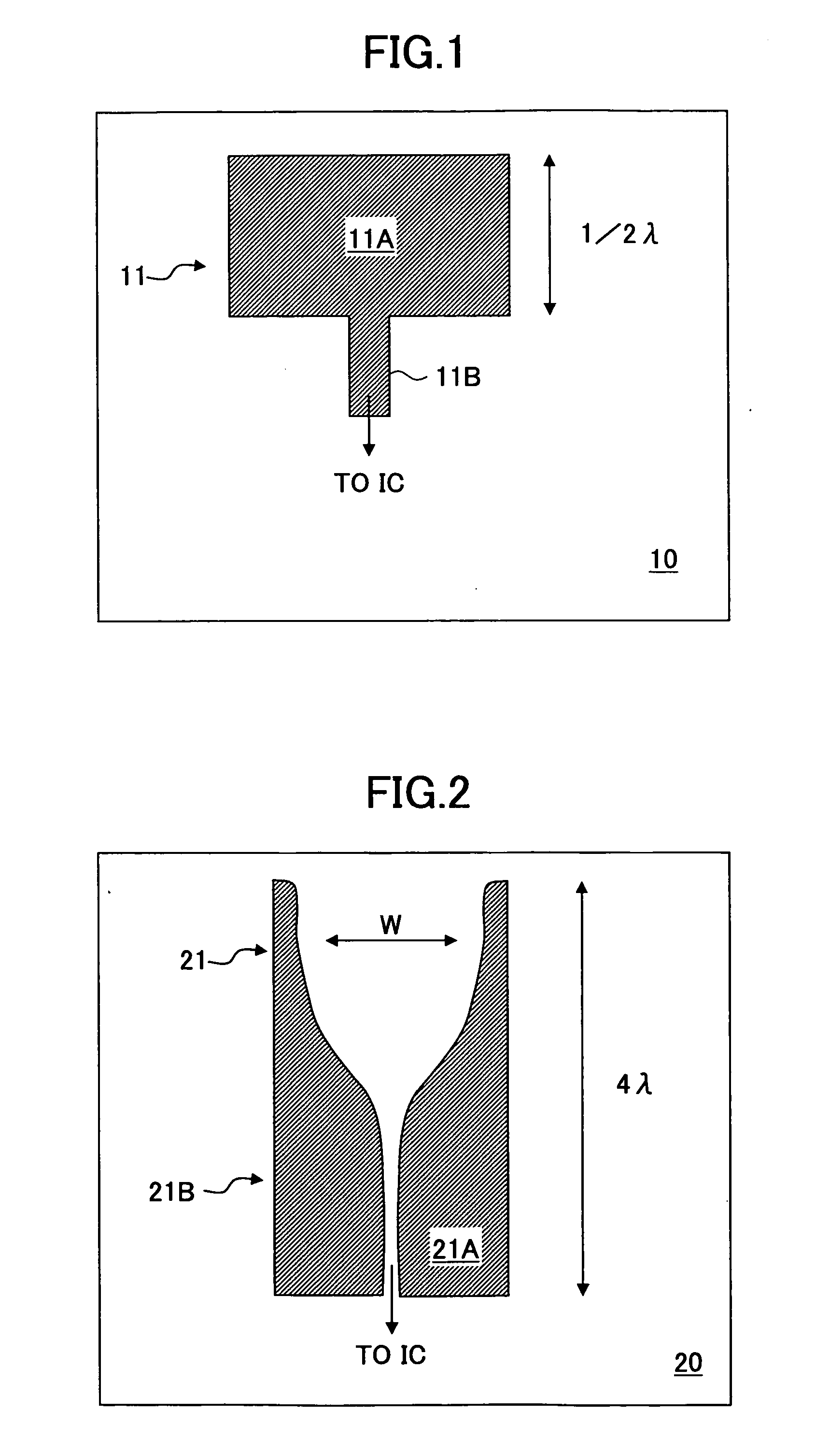
[0013] Such a patch antenna 11 has an advantageous feature of simple construction, occupying a small area and has further advantage of easy designing. On the other hand, such a patch antenna naturally suffers from the problem of low antenna gain and non-directivi

Problems solved by technology

On the other hand, such a patch antenna naturally suffers from the problem of low antenna gain and non-directivity within t

Method used


Image

  • Planar antenna and radio apparatus
  • Planar antenna and radio apparatus
  • Planar antenna and radio apparatus

Examples


first embodiment

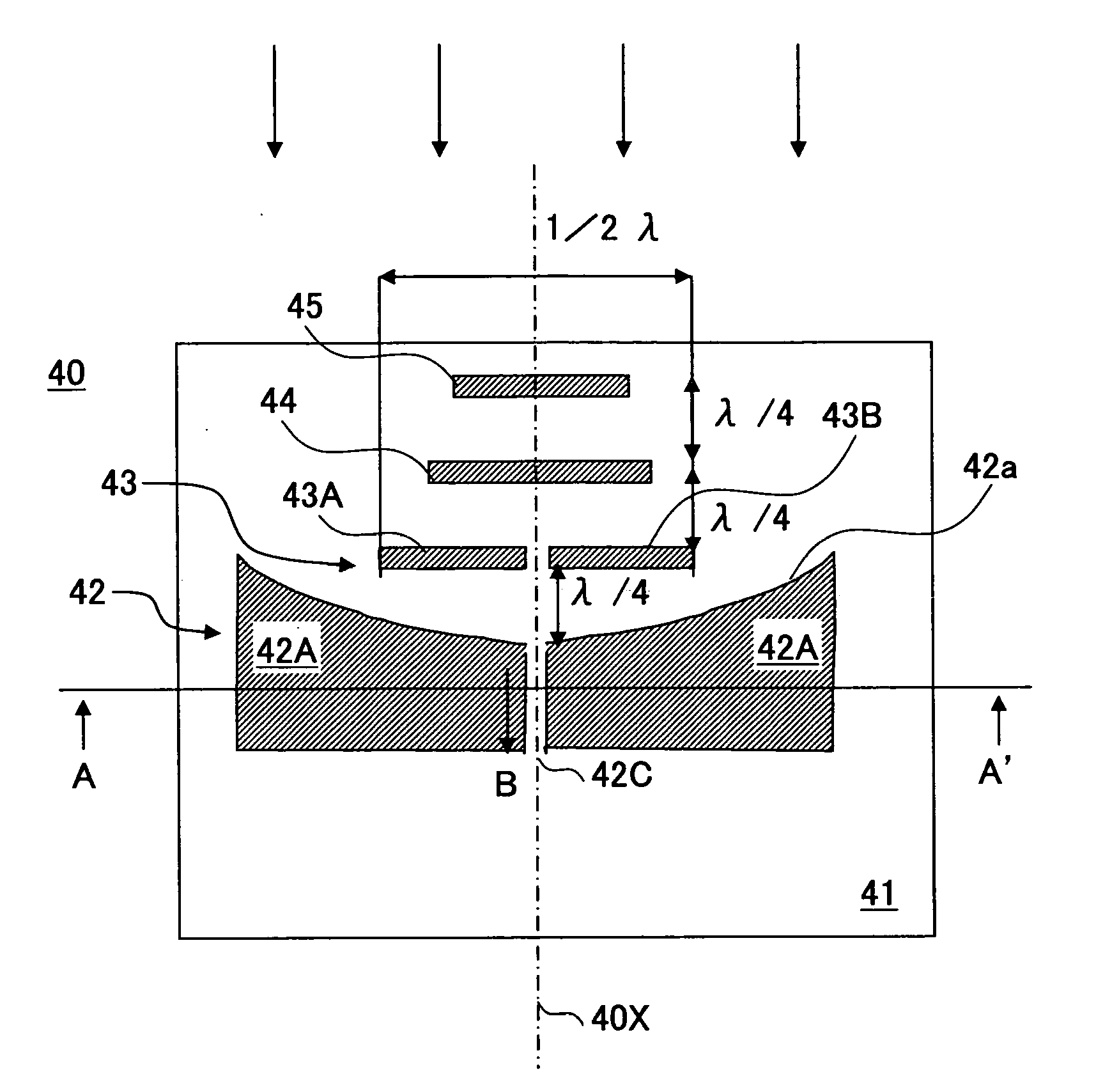
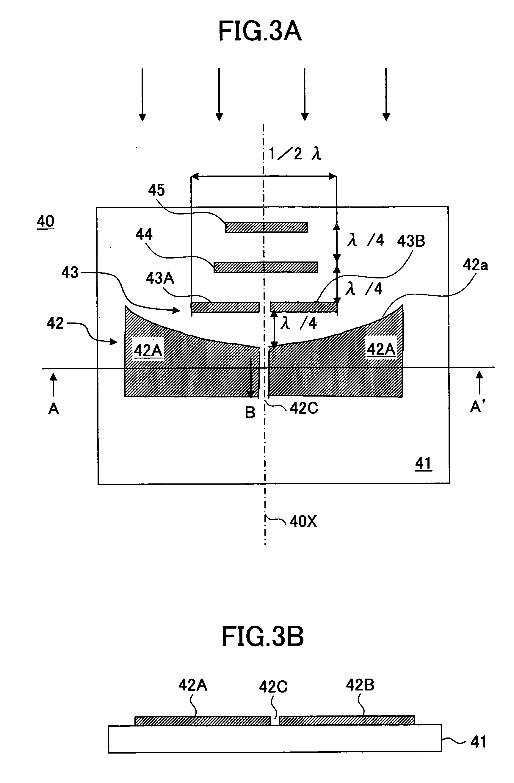
[0033]FIG. 3A is a plan view diagram of a planar antenna 40 according to a first embodiment of the present invention, while FIG. 3B shows the same planar antenna in a cross-sectional view taken along a line A-A′ of FIG. 3A.

[0034] Referring to FIGS. 3A and 3B, the planar antenna 40 is formed on a low-loss circuit substrate 41 of ceramics, quartz glass or resin, wherein there is provided a slot line 42 on the circuit substrate 41 by conductor patterns 42A and 42B of Au, Cu, or the like, wherein the slot line 42 includes a slot 42C between the conductor patterns 42A and 42B and an electromagnetic wave of the frequency of typically in the order of 100 GHz (millimeter wave) is guided along the slot 42C in an axial direction 40x thereof as represented by an arrow B.

[0035] It should be noted that the slot line 42 has a curved end part 42a forming a generally parabolic shape in the illustrated example, wherein it should be noted that the curved shape of the end part 42a is determined such...

second embodiment

[0044]FIG. 5 shows the construction of a radio apparatus 50 that uses the planar antenna 40 according to a second embodiment of the present invention, wherein those parts corresponding to the parts described previously are designated by the same reference numerals and the description thereof will be omitted.

[0045] Referring to FIG. 5, the radio apparatus 50 is a receiver such as a passive radar set constructed on the circuit substrate 41 for detecting feeble incoming millimeter waves and includes a semiconductor chip 51 flip-chip mounted on the conductor patterns 42A and 42B constituting the planar antenna 40. It should be noted that the semiconductor chip 51 includes therein a low-noise amplifier and amplifies the electromagnetic wave collected by the planar antenna 40 and injected into the slot line 42 with high gain.

[0046] In the construction of FIG. 5, there is formed a coplanar line 421 in continuation with the slot line 42 that forms the planar antenna 40, and the semiconduc...


PUM


Abstract

A planar antenna is formed of a circuit substrate and a slot line formed on the circuit substrate for guiding an electromagnetic wave in an axial direction thereof, the planar antenna emitting the electromagnetic wave at an end part of said slot line, wherein the end part has a curved shape forming a focal point at a location on an axis of the slot line with offset by a distance of about a quarter wavelength of the electromagnetic wave, and wherein there is provided a conductor pattern having a length of about a half of the wavelength of the electromagnetic wave at the focal point.

Description

CROSS-REFERENCE TO RELATED APPLICATION [0001] The present application is based on Japanese priority application No.2004-273943 filed on Sep. 21, 2004, the entire contents of which are hereby incorporated by reference. BACKGROUND OF THE INVENTION [0002] The present invention generally relates to radio apparatuses and more particularly to a planar antenna formed on a circuit substrate and a radio apparatus having such a planar antenna. [0003] Investigations are being made on a planar antenna formed integrally on a circuit substrate in relation to radar sets of millimeter wavelength band. On the other hand, such a planar antenna is also important in the field of radio astronomy. [0004] Conventionally, high-performance antennas that use a waveguide have been used for the reception of millimeter wavelength band radio signals. [0005] However, such an antenna that uses a waveguide forms a three-dimensional circuit of heavy weight, and raises the problem of high cost. In addition, such an a...

Claims


Application Information

Patent Timeline
IPC IPC(8): H01Q13/10
CPCH01Q1/38H01Q13/085H01Q19/32
Inventor SATO, MASARU
Owner FUJITSU LTD
Why Eureka
Try Eureka