Photoelectric composite interconnection assembly and electronics device using same

US20060067608A1Inactive Publication Date: 2006-03-30HITACHI CABLE

Image

  • Photoelectric composite interconnection assembly and electronics device using same
  • Photoelectric composite interconnection assembly and electronics device using same
  • Photoelectric composite interconnection assembly and electronics device using same

Examples


Embodiment Construction

[0059] Preferred embodiments of the present invention will be described hereinafter by referring to the accompanying drawings.

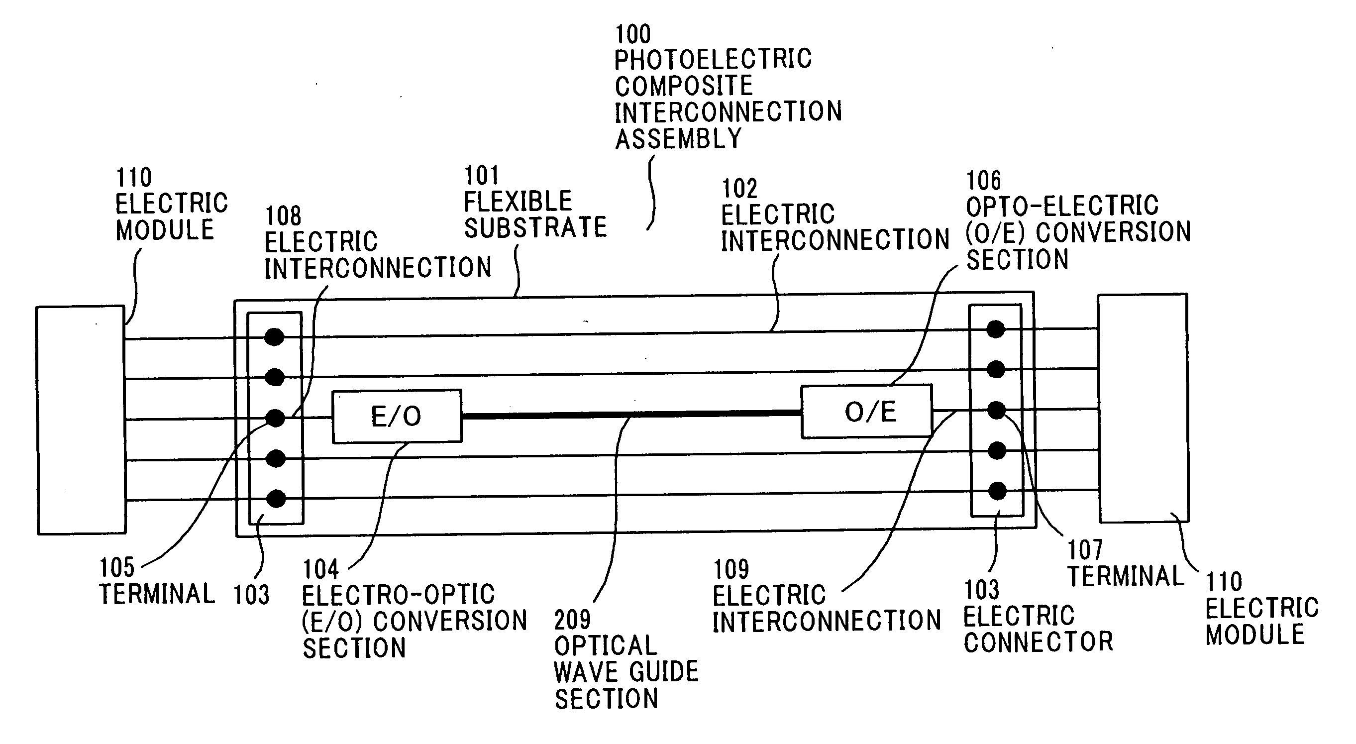
[0060]FIG. 5 is a top view showing the whole construction of a photoelectric composite interconnection assembly 100 of the invention, and FIG. 6A is a sectional view showing the photoelectric composite interconnection assembly 100 of the invention.

[0061] In the photoelectric composite interconnection assembly 100, electric interconnections 102 made of a copper material are provided on a flexible substrate 101 having flexibility and optical transparency, and electric connectors 103 each having a plurality of terminals are provided at both ends of the flexible substrate 101. The electric connector 103 interfaces in between respective electronic modules to transmit electrical signals between them. A polymer material is desirable as a material for the flexible substrate 101 having flexibility and optical transparency, and a specific example of the polymer mater...


PUM


Abstract

A photoelectric composite interconnection assembly having: a flexible substrate having an electric interconnection; and an electrical interface provided at both ends of the electric interconnection. A part of the electric interconnection is replaced by an optical transmission line.

Description

[0001] The present application is based on Japanese patent application No. 2004-274671, the entire contents of which are incorporated herein by reference. BACKGROUND OF THE INVENTION [0002] 1. Field of the Invention [0003] This invention relates to a photoelectric composite interconnection assembly and, particularly, to a photoelectric composite interconnection assembly with flexibility, and further relates to an electronics device using the same. [0004] 2. Description of the Related Art [0005] The developments of high-speed and high-capacity communication technology are actively advanced with expansion of services and applications for handling high-capacity data such as picture images in telecommunication equipment such as personal computers and cellular phones. Under the circumstances, the developments of interconnections that allow high-speed and high-capacity communications at a high density inside an electronics device or among electronics devices attract attention. [0006] A co...

Claims


Application Information

Patent Timeline
30 Mar 2006
Publication
US20060067608A1
IPC
G02B6/12
CPC
G02B6/10; G02B6/12004; G02B6/1221; H01L2224/16225; G02B6/4214; G02B2006/12104; G02B6/42; H01L2924/00014
Inventors
KOBAYASHI, MASAHIKO; HIRUTA, AKIHIRO