Optical image measuring apparatus

Inactive Publication Date: 2006-04-06
KK TOPCON
View PDF4 Cites 27 Cited by
  • Summary
  • Abstract
  • Description
  • Claims
  • Application Information

AI Technical Summary

Benefits of technology

[0034] According to a first aspect of the present invention, there is provided an optical image measuring apparatus, including: light beam outputting means for selectively outputting one of a plurality of light beams having different wavelengths, intensities of the light beams being periodically modulated; first converting means for converting a polarization characteristic of the outputted one of the light beams to linear polarization; dividing means for dividing the outputted one of the light beams into signal light propagating through an object to be measured and reference light propagating through a reference object; second converting means for converting a polarization characteristic of one of the signal light and the reference light, which is the linear polarization; frequency shifting means for shifting a frequency of the signal light and a frequency of the reference light relative to each other; superimposing means for superimposing the signal light propagating through the object to be measured and the reference light propagating through the reference object on each other to produce interference light in which each of the signal light and the reference light includes a polarization characteristic converted by the first converting means and the second converting means and the frequency of the signal light and the frequency of the reference light are shifted by the frequency shifting means; extracting means for extracting a plurality of polarized light components from the produced interference light, the polarized light components being different from one another; two-dimensional detection means for detecting each of the polarized light components extracted from the interference light; and image forming means for forming an image of the object to be measured based on a result obtained by the two-dimensional detection means with respect to each of at least two light beams of the plurality of light beams having the different wavelengths. Therefore, when the wavelengths of the light beams used for image formation are set as appropriate, it is possible to obtain an image expressing functional information such as the oxygen saturation of hemoglobin. At this time, because the polarized light components of the interference light can be effectively detected using the two-dimensional detection means, a two-dimensional image of the object to be measured at a depth thereof is obtained at a time without being scanned with the signal lig

Problems solved by technology

In addition, it is hard to shorten a measurement time in view of measurement fundamentals.
Therefore, it is supposedly hard to actually use the apparatus in fields that require a high resolution image, such as a medical field and an industrial field.
However, up to now, a problem has been recognized that a currently available CCD camera cannot follow the beat frequency of a heterodyne signal which is the order of several kHz to several MHz because of the low frequency response characteristic thereof.
According to this apparatus, en

Method used


Image

  • Optical image measuring apparatus
  • Optical image measuring apparatus
  • Optical image measuring apparatus

Examples


first embodiment

[Structure of Apparatus]

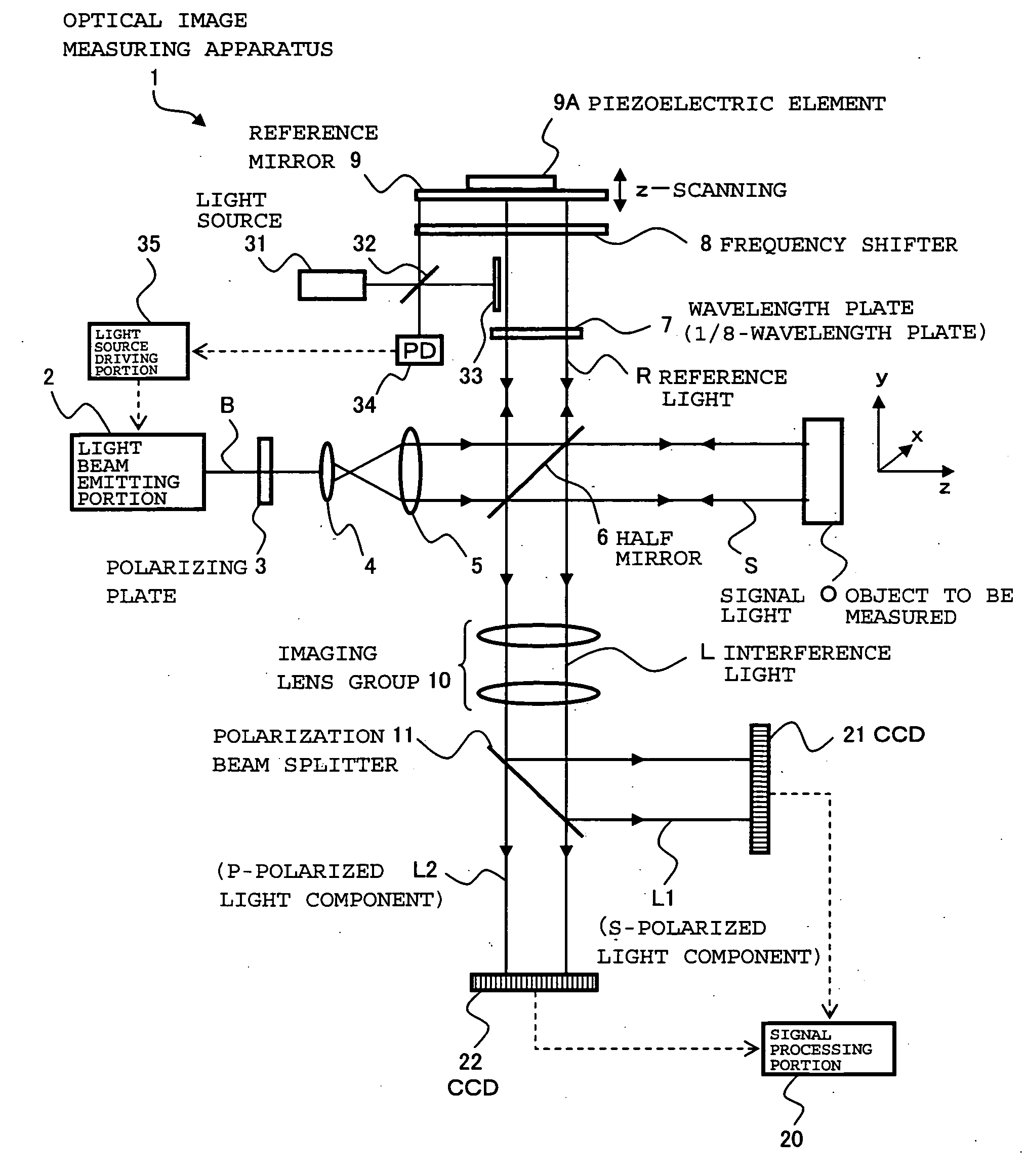
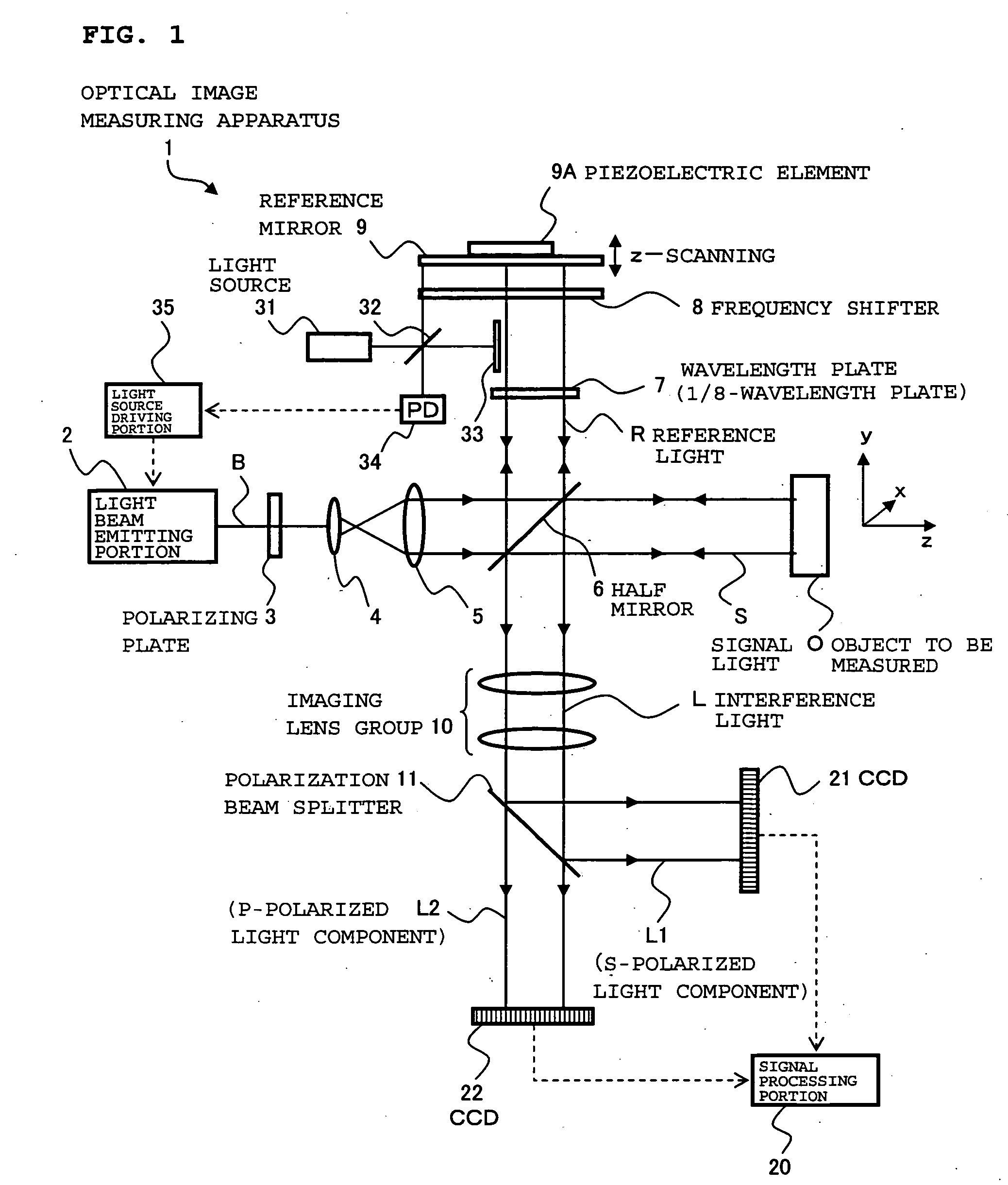
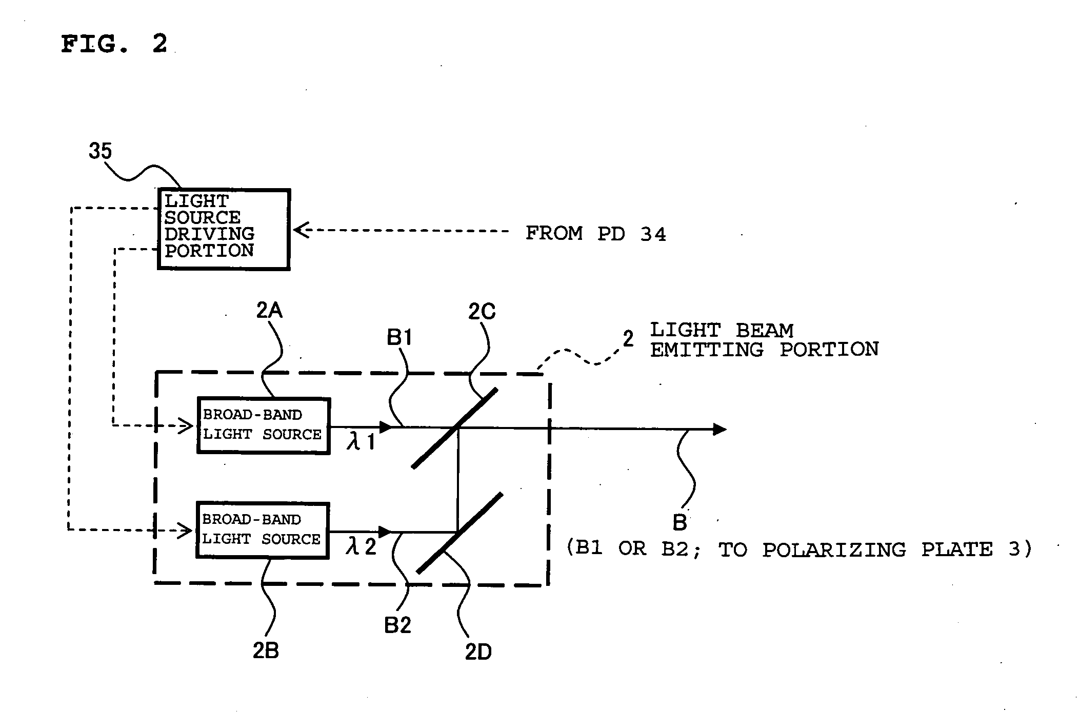
[0048] First, an optical image measuring apparatus according to the first embodiment of the present invention will be described in detail with reference to FIGS. 1 to 4. FIG. 1 illustrates a structure of (mainly) an optical system of an optical image measuring apparatus 1 according to this embodiment. FIG. 2 illustrates a structure of a light beam emitting portion 2 in the optical system of the optical image measuring apparatus 1. FIG. 3 illustrates a structure of a control system of the optical image measuring apparatus 1. FIGS. 4A to 4E are explanatory diagrams showing processing for generating drive signals for the light beam emitting portion 2 of the optical image measuring apparatus 1.

[Structure of Optical System]

[0049] As shown in FIG. 1, the optical image measuring apparatus 1 includes a light beam emitting portion 2 for selectively outputting one of a plurality of light beams having different wavelengths in which the intensities of the light beams ...

second embodiment

[0144] Subsequently, an optical image measuring apparatus according to a second embodiment of the present invention will be described. In this embodiment, the interference light M is sampled using shutters.

[Structure of Apparatus]

[0145] First, the optical image measuring apparatus according to this embodiment will be described. FIG. 6 illustrates (mainly) an optical system of the optical image measuring apparatus according to this embodiment and FIG. 7 illustrates a control system thereof. Hereinafter, the same reference numerals and symbols are provided to the same constituent portions as those in the first embodiment.

[Structure of Optical System]

[0146] Referring to FIG. 6, as in the first embodiment, an optical image measuring apparatus 100 according to this embodiment includes the light beam emitting portion 2, the lenses 4 and 5, the half mirror 6 (dividing means and superimposing means), the frequency shifter 8 (frequency shifting means), the reference mirror 9 (reference o...


PUM


Abstract

An optical image measuring apparatus forming an image expressing functional information on a living tissue. The optical image measuring apparatus includes a light emitting portion (2) outputting light (B1 and B2(B)) having different wavelengths intensity-modulating the light periodically, a polarizing plate (3) converting a light (B) to linearly polarized light, a half mirror (6) dividing the light (B) into signal light (S) and reference light (R), a wavelength plate (7) converting a polarization characteristic of the reference light (R), a frequency shifter (8) shifting a frequency of the reference light (R), the half mirror (6) superimposing the signal light (S) and the reference light (R) on each other to produce interference light (L), a polarization beam splitter (11) extracting a polarized light from the interference light (L), CCDs (21 and 22) detecting the extracted polarized interference light (L), and a signal processing portion (20) forming an image of an object to be measured (O) based on the polarized interference light (L) related to each of the light (B1 and B2), detected by the CCDs (21 and 22).

Description

BACKGROUND OF THE INVENTION [0001] 1. Field of the Invention [0002] The present invention relates to an optical image measuring apparatus that applies a light beam to an object to be measured, particularly a light scattering medium, and produces a surface form or inner form of the object to be measured by detecting a reflected light beam or a transmitted light beam. In particular, the present invention relates to an optical image measuring apparatus for measuring the surface form or inner form of the object to be measured by using an optical heterodyne detection method to produce the image of the measured form. [0003] 2. Description of the Related Art [0004] In recent years, attention has been given to optical imaging technique that produces an image of a surface or inner portion of an object to be measured using a laser light source or the like. This optical imaging technique is not hazardous to human bodies in contrast to the conventional X-ray CT. Therefore, the development of ap...

Claims


Application Information

Patent Timeline
IPC IPC(8): G01B9/02
CPCA61B5/0066A61B5/14546A61B5/14551G01N21/21G01N21/3151G01N21/359G01N21/4795G01N2021/1772G01N2021/1787G01N2201/0691G01B9/02012G01B9/02007G01B9/02002G01B9/02091G01B9/02069G01B2290/70G01B9/02081G01B2290/45G01N21/3563
Inventor CHAN, KINPUIAKIBA, MASAHIRO
Owner KK TOPCON
Why Eureka
Try Eureka