
Method, program product and apparatus for model based scattering bar placement for enhanced depth of focus in quarter-wavelength lithography

Active Publication Date: 2006-04-06
ASML NETHERLANDS BV
View PDF27 Cites 31 Cited by
  • Summary
  • Abstract
  • Description
  • Claims
  • Application Information

AI Technical Summary

Benefits of technology

[0020] Another advantage of the present invention is that it provides a model-based system for determining the optimal (i.e., maximum) size of the assist features, thereby further enhancing the resulting OPC performance.

Problems solved by technology

These rules are set by processing and design limitations.
Obviously, the more factors considered, the more complex the rules become.
The rules-based approach does not adapt itself well to complicated designs where a two-dimensional analysis is preferred.
As a result, rules based on a two-dimensional analysis are very difficult to formulate and express, and generally lead to very complicated multi-dimensional matrices.
However, for IC design rules (expressed in half feature pitch) beyond one-third of illumination wavelength, λ, such as 45 nm and 32 nm technology nodes, conventional optics (numerical aperture, or NA<1) can no longer attain sufficient resolution and the desired depth of focus (DOF) for lithography manufacturing.
This is barely adequate from the point of view of focal plane leveling capability limit with advanced mechanical wafer stage.

Method used


Image

  • Method, program product and apparatus for model based scattering bar placement for enhanced depth of focus in quarter-wavelength lithography
  • Method, program product and apparatus for model based scattering bar placement for enhanced depth of focus in quarter-wavelength lithography
  • Method, program product and apparatus for model based scattering bar placement for enhanced depth of focus in quarter-wavelength lithography

Examples


first embodiment

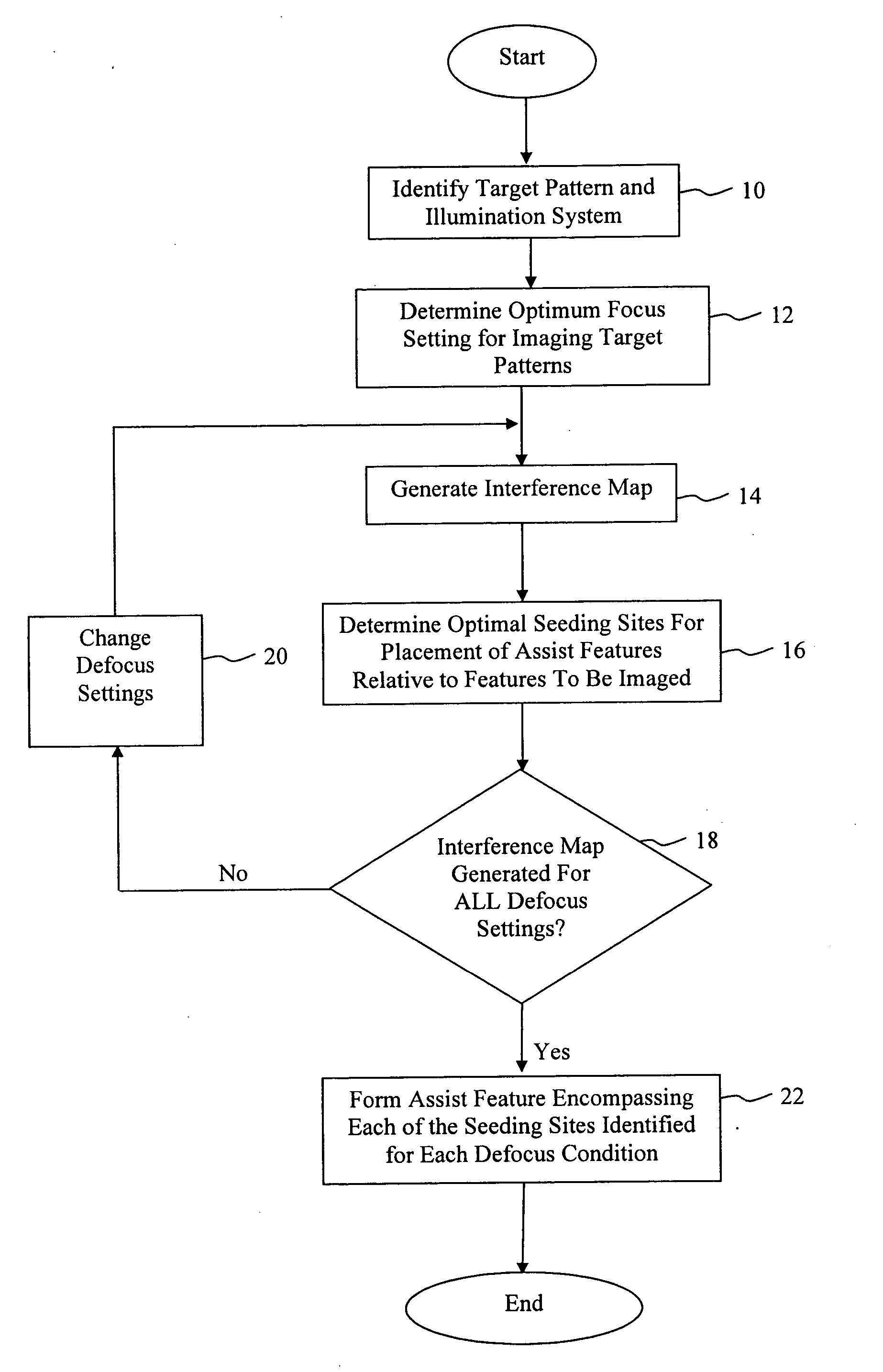
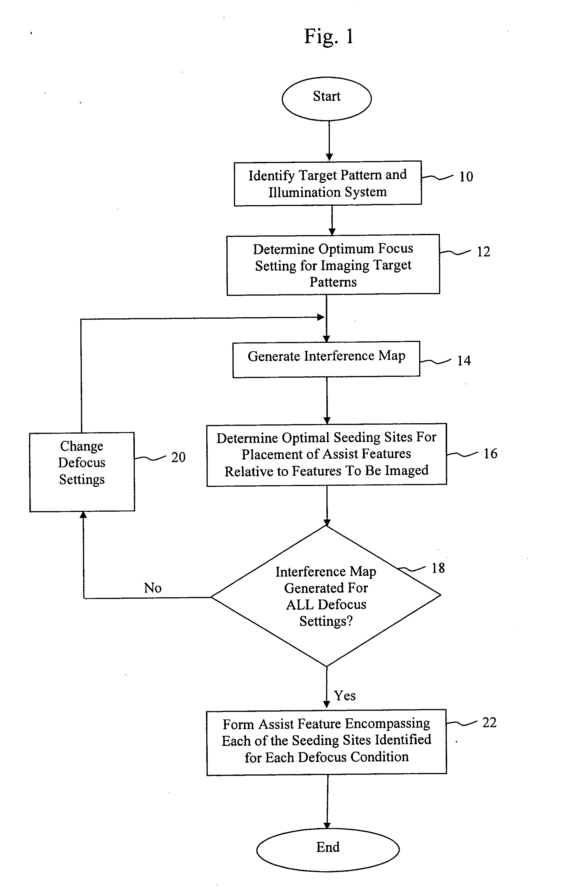
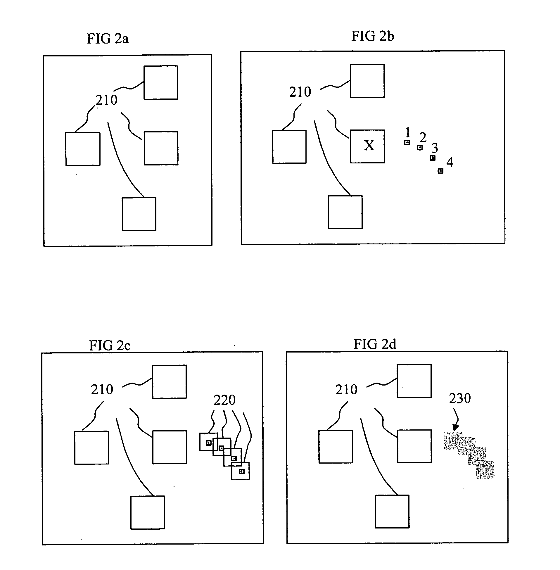
[0035]FIG. 1 is an exemplary flowchart illustrating the method of applying assist features to a mask pattern in accordance with the present invention. The first step (Step 10) in the process is to identify the target mask pattern and illumination system and settings to be utilized to image the pattern. An exemplary target pattern comprising contact holes 210 is shown in FIG. 2a. The next step (Step 12) in the process is to determine the optimal focus setting for imaging the target pattern utilizing the given imaging system. As is known, the optimum focus setting can be determined either by a calibration or simulation process. The next step in the process (Step 14) is to generate an interference map (IM) for the target pattern utilizing the optimum focus setting. As noted above, the interference map can be generated in the manner disclosed in U.S. patent application Ser. No. 10 / 756,830. Once the interference map is generated, it is utilized to determine the optimal seeding sites for ...

second embodiment

[0042] In the present invention, a process is disclosed for optimizing the size and shape of the assist features disposed in the target pattern. As is known, for most robust assist feature performance, it is desirable to form the assist features as large as possible. Moreover, larger assist feature dimensions result in an easier mask manufacturing process. However, as noted above, the assist feature must not be printable under nominal printing conditions for the CD target features. Known prior art methods typically utilized a traditional rule-based approach to define the size of the assist feature, where X & Y size limits where predefined. While such approaches have been effective, it is more desirable to be able to tune the X and Y dimension of the assist feature according to the optical neighbors, especially when utilizing the assist feature generation method discussed above, which can produce assist features having very irregular shapes, such as shown in FIG. 3. Indeed, when util...

third embodiment

[0051] In the present invention, the interference map is utilized to determine whether the given features in the target pattern represent strong or weak features with respect to imaging performance. More specifically, the interference map is analyzed to determine the intensity of the interference at the locations of the features within the mask. Features located at positions having high levels of interference are considered strong features that will image easily. Alternatively, features located at positions exhibiting reduced levels of interference may exhibit unacceptable imaging results. Once defined, as explained in detail below, additional steps can be taken to ensure acceptable printing of the weak features.

[0052]FIG. 7 illustrates a flowchart describing the method of defining features to be imaged as either a weak feature or a string feature with respect to the imaging process. The first step (Step 710) is to define the target pattern and the illumination system to be utilized...


PUM


Abstract

A method of generating a mask having optical proximity correction features. The method includes the steps of: (a) obtaining a desired target pattern having features to be imaged on a substrate; (b) determining a first focus setting to be utilized when imaging the mask; (c) determining a first interference map based on the target pattern and the first focus setting; (d) determining a first seeding site representing the optimal placement of an assist feature within the mask relative to a feature to be imaged on the basis of the first interference map; (e) selecting a second focus setting which represents a predefined amount of defocus relative to the first focus setting; (f) determining a second interference map based on the target pattern and the second focus setting; (g) determining a second seeding site representing the optimal placement of an assist feature within the mask relative to the feature to be imaged on the basis of the second interference map; and (h) generating an assist feature having a shape which encompasses both the first seeding site and the second seeding site.

Description

CLAIM OF PRIORITY [0001] This patent application, and any patent(s) issuing therefrom, claims priority to U.S. provisional patent application No. 60 / 603,560, filed on Aug. 24, 2004, entitled “Method Of Model Based Scattering Bars For Enhanced Depth Of Focus In Quarter-Wavelength Lithography”, which is incorporated herein by reference in its entirety.TECHNICAL FIELD [0002] The technical field of the present invention relates generally to a method, program product and apparatus for generation and placement of assist features within a target pattern to provide OPC and improve overall imaging performance. BACKGROUND OF THE INVENTION [0003] Lithographic apparatus can be used, for example, in the manufacture of integrated circuits (ICs). In such a case, the mask may contain a circuit pattern corresponding to an individual layer of the IC, and this pattern can be imaged onto a target portion (e.g., comprising one or more dies) on a substrate (silicon wafer) that has been coated with a laye...

Claims


Application Information

Patent Timeline
IPC IPC(8): G03C5/00G06F17/50G03F1/00G03F1/36
CPCG03F1/144G03F1/36G03F7/70441G03F7/20
Inventor BROEKE, DOUGLAS VAN DENCHEN, JANG FUNG
Owner ASML NETHERLANDS BV
Learn More