High efficiency emitter for incandescent light sources

a technology of emitter and incandescent light source, which is applied in the direction of discharge tube/lamp details, non-electron-emitting electrode materials, lamp incadescent bodies, etc., can solve the problems of limited efficiency of traditional incandescent lamps, achieve selective absorption, enhance the luminous efficiency of the emitter, and minimise the angular sensitivity of the grating

Inactive Publication Date: 2006-04-13
CENT RICERCHE FIAT SCPA
View PDF12 Cites 26 Cited by
  • Summary
  • Abstract
  • Description
  • Claims
  • Application Information

AI Technical Summary

Benefits of technology

[0028] As stated, the solution according to the present invention consists of structuring the surface of the emitter, which is preferably in plate form with parallel faces, but can also be in the form of a wire, cylindrical or with any other cross section, with the three-dimensional micro-structure having periodicity below the visible wavelength and such as to increase absorption selectively, mainly in the visible region of the spectrum. This allows, at equal equilibrium temperature, to increase the portion of radiation emitted in the visible region, increasing the portion emitted in the infrared region to a lesser extent than the visible portion and thereby enhancing the luminous efficiency of the emitter. In general terms, the dimensions of the emitter according to the invention, both in terms of total thickness and of depth/height of the micro-projections or of the micro-cavities, are in the order of tens or hun...

Problems solved by technology

The efficiency of traditional incandescent lamps is limited by Planck's law, which describes the spectral intensity I(λ) of the radi...

Method used


Image

  • High efficiency emitter for incandescent light sources
  • High efficiency emitter for incandescent light sources
  • High efficiency emitter for incandescent light sources

Examples


Embodiment Construction

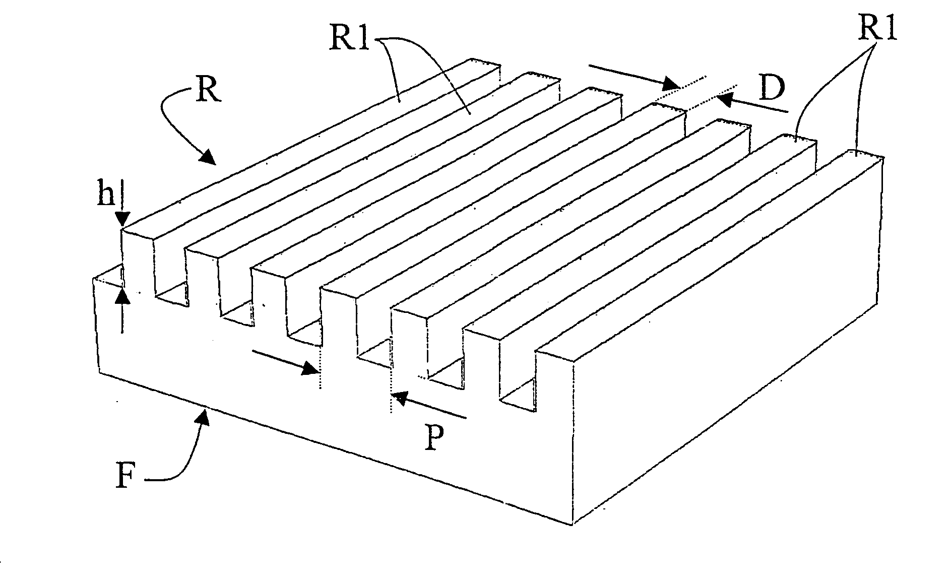
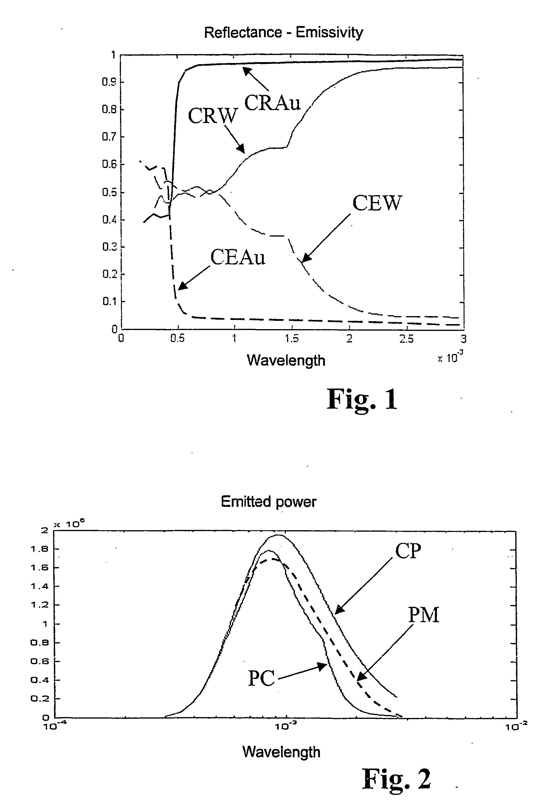
[0045] As previously explained, according to the main aspect of the present invention, the increase in efficiency of visible emission is obtained by means of an appropriate micro-structuring of the surface of the incandescence emitter; said micro-structuring is operative to reduce the reflectance ρ in the visible region of the spectrum, reducing the reflectance ρ in the near infrared region to a lesser extent, in order to increase emission efficiency in the visible region.

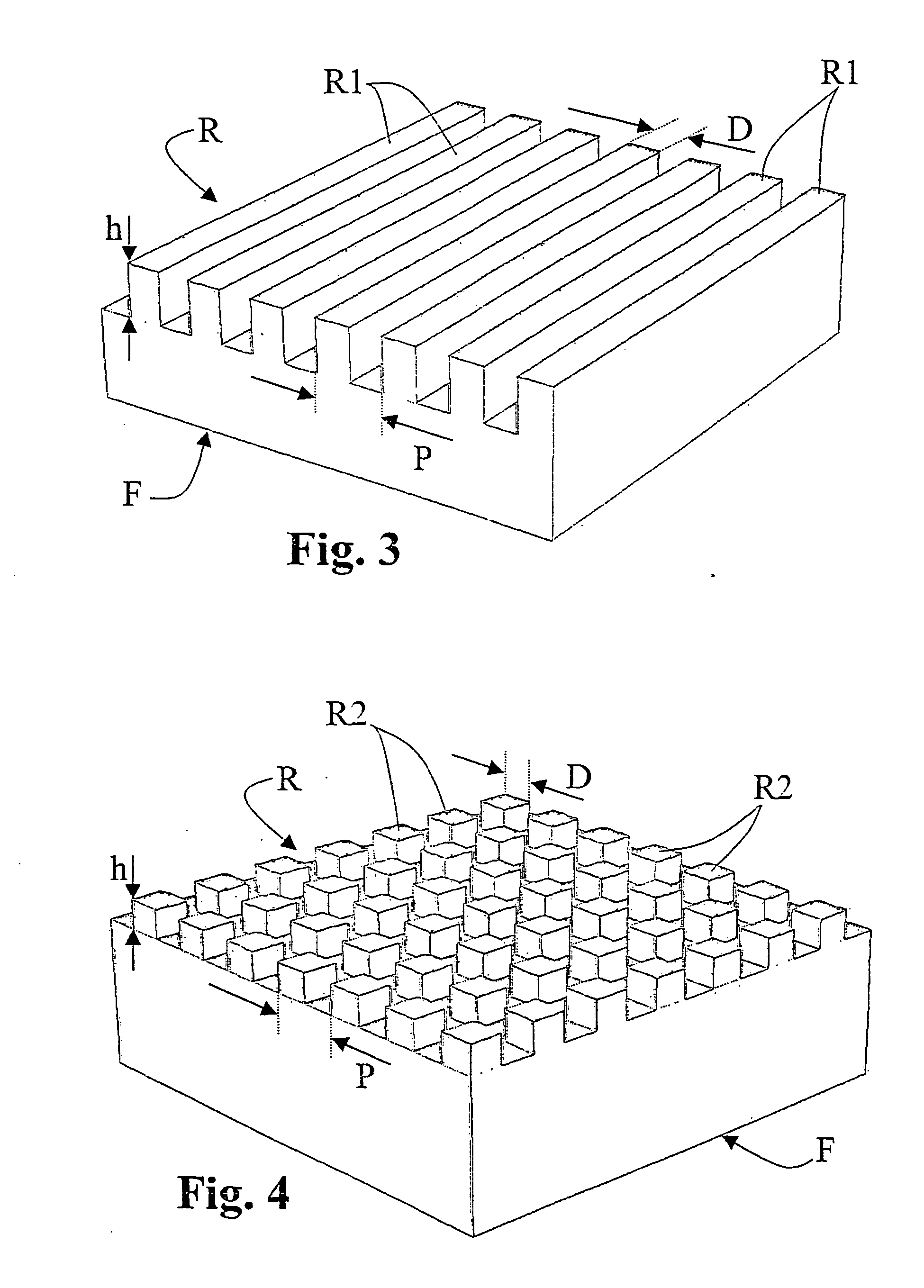
[0046] The desired anti-reflection behaviour can be obtained both with a one-dimensional grating, i.e. with periodic projections along a single direction on the surface of the filament, both with a two-dimensional diffraction grating, i.e. with periodic projections along two orthogonal directions, not being necessarily parallel to each other, on the surface of the filament. For this purpose, in FIG. 3 the reference F designates a portion of an emitter according to the invention, which superficially has a diffracti...


PUM


Abstract

An emitter (F) for incandescent light sources, in particular a filament, capable of being brought to incandescence by the passage of electric current is obtained in such a way as to have a value of spectral absorption α that is high in the visible region of the spectrum and low in the infrared region of the spectrum, said absorption α being defined as α=1−ρ−T, where ρ is the spectral reflectance and T is the spectral transmittance of the emitter.

Description

FIELD OF THE INVENTION [0001] The present invention relates to an emitter for incandescent light sources, in particular shaped as a filament or a plate, capable of being brought to incandescence by the passage of electric current. BACKGROUND OF THE INVENTION [0002] As is known, traditional incandescent lamps are provided with a tungsten (W) filament which is made incandescent by the passage of electric current. The efficiency of traditional incandescent lamps is limited by Planck's law, which describes the spectral intensity I(λ) of the radiation emitted by the tungsten filament of the lamp at the equilibrium temperature T, and by heat losses through conduction and convection. The energy irradiated by the tungsten filament in the visible range of the electromagnetic spectrum is proportional to the integral of the curve I(λ) between λ1=380 nm and λ2=780 nm, and is at the most equal to 5-7% of the total energy. [0003] According to Kirchoff's law, under thermal equilibrium conditions t...

Claims


Application Information

Patent Timeline
IPC IPC(8): H01K1/14H01KH01K1/04H01K3/02H03F3/217H03F3/38
CPCH01K1/04H01K1/14H01K3/02
Inventor PULLINI, DANIELEREPETTO, PIERMARIODOSKLOVICH, LEONIDBERNARD, STEFANOLAMBERTINI, VITOPERLO, PIEROCAPELLO, DAVIDEBRIGNONE, MAUROLI PIRA, NELLO
Owner CENT RICERCHE FIAT SCPA
Why Eureka
Try Eureka