Gas operated pump for hydrocarbon wells

a technology of hydrocarbon wells and pumps, which is applied in the direction of non-positive displacement pumps, wellbore/well accessories, fluid removal, etc., can solve the problems of limiting the injectivity of fluid (heated or cold) into the formation, reducing production, and reducing the production of hydrocarbons, so as to improve hydrocarbon production and production. , the effect of improving production

Inactive Publication Date: 2006-04-20
WEATHERFORD TECH HLDG LLC
View PDF43 Cites 79 Cited by
  • Summary
  • Abstract
  • Description
  • Claims
  • Application Information

AI Technical Summary

Problems solved by technology

Throughout the world there are major deposits of heavy oils which, until recently, have been substantially ignored as sources of petroleum since the oils contained therein were not recoverable using ordinary production techniques.
Furthermore, oil saturations in these formations are typically large which limits the injectivity of a fluid (heated or cold) into the formation.
At this stage, further steam injection may be terminated and production declines until the wells are abandoned.
Although the SAGD operation has been effective in recovering a large portion of “tar sand” or “heavy oil” deposits, the success of complete recovery of the deposits is often hampered by the inability to effectively move the viscous deposits up the production tubing.
However, the ESP tends to gas lock in high temperature conditions.
The rod pump can operate in high temperatures but cannot handle the large volume of oil.
The gas-operated pump is effective in low pressure and low temperature but has low volume capacity.
Due to this problem many wells using the SAGD operation are not recovering the maximum amount of deposits available in the reservoir.
Several other recovery methods have problems similar to a SAGD operation due to an inadequate pumping device.
The process of removing and re-inserting the pump after the first step is very costly due to the expense of a workover.
In these conditions, the ESP pump cannot operate reliably due to the high temperature.
The rod pump can operate in high temperature but has a limited capacity to move a high volume of oil.
The recovery operation to remove water containing dissolved methane is often hampered by the inability of the pumping device to handle the low pressure and the abrasive material which are characteristic of a gas well in a coal bed methane application.

Method used


Image

  • Gas operated pump for hydrocarbon wells
  • Gas operated pump for hydrocarbon wells
  • Gas operated pump for hydrocarbon wells

Examples


Embodiment Construction

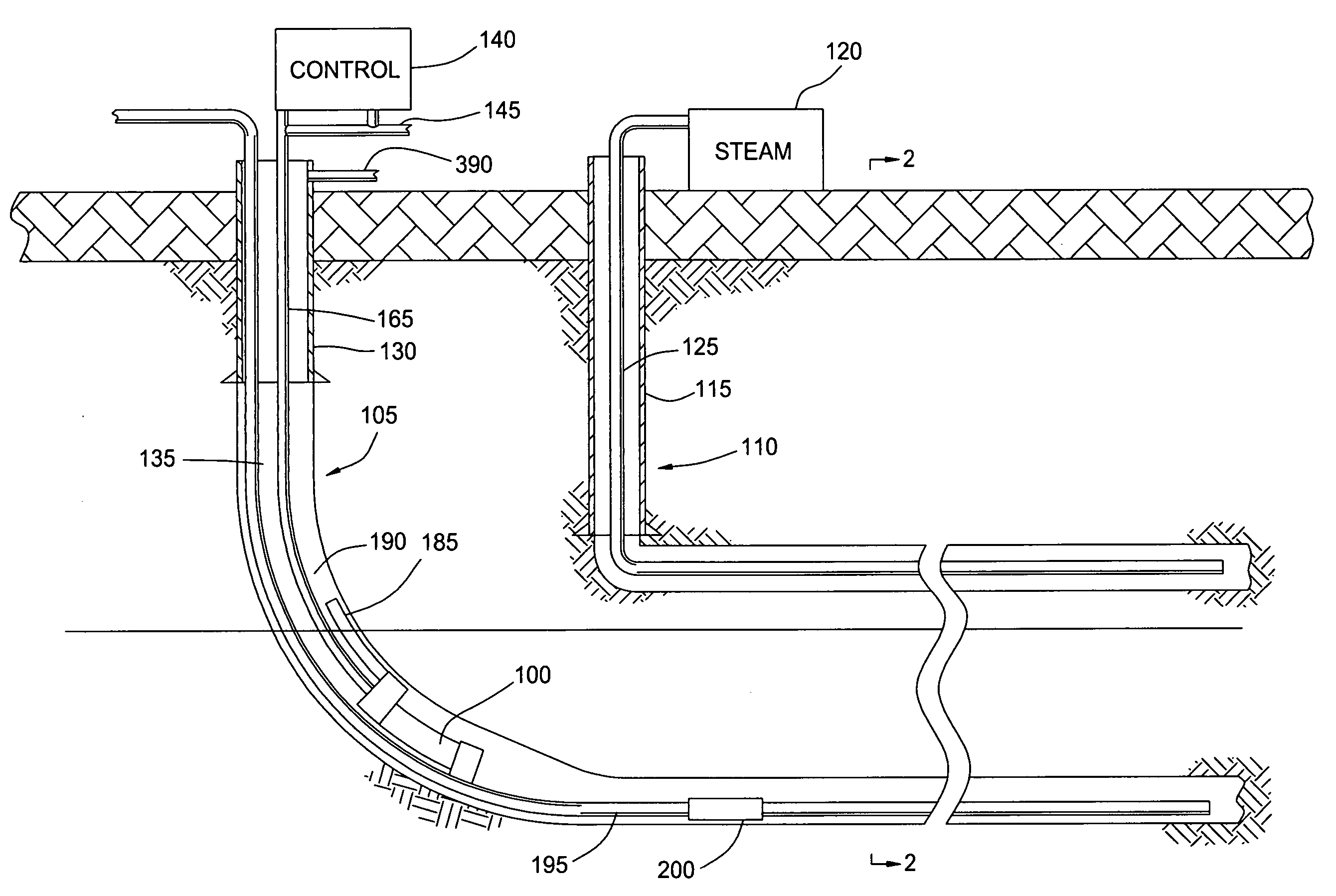
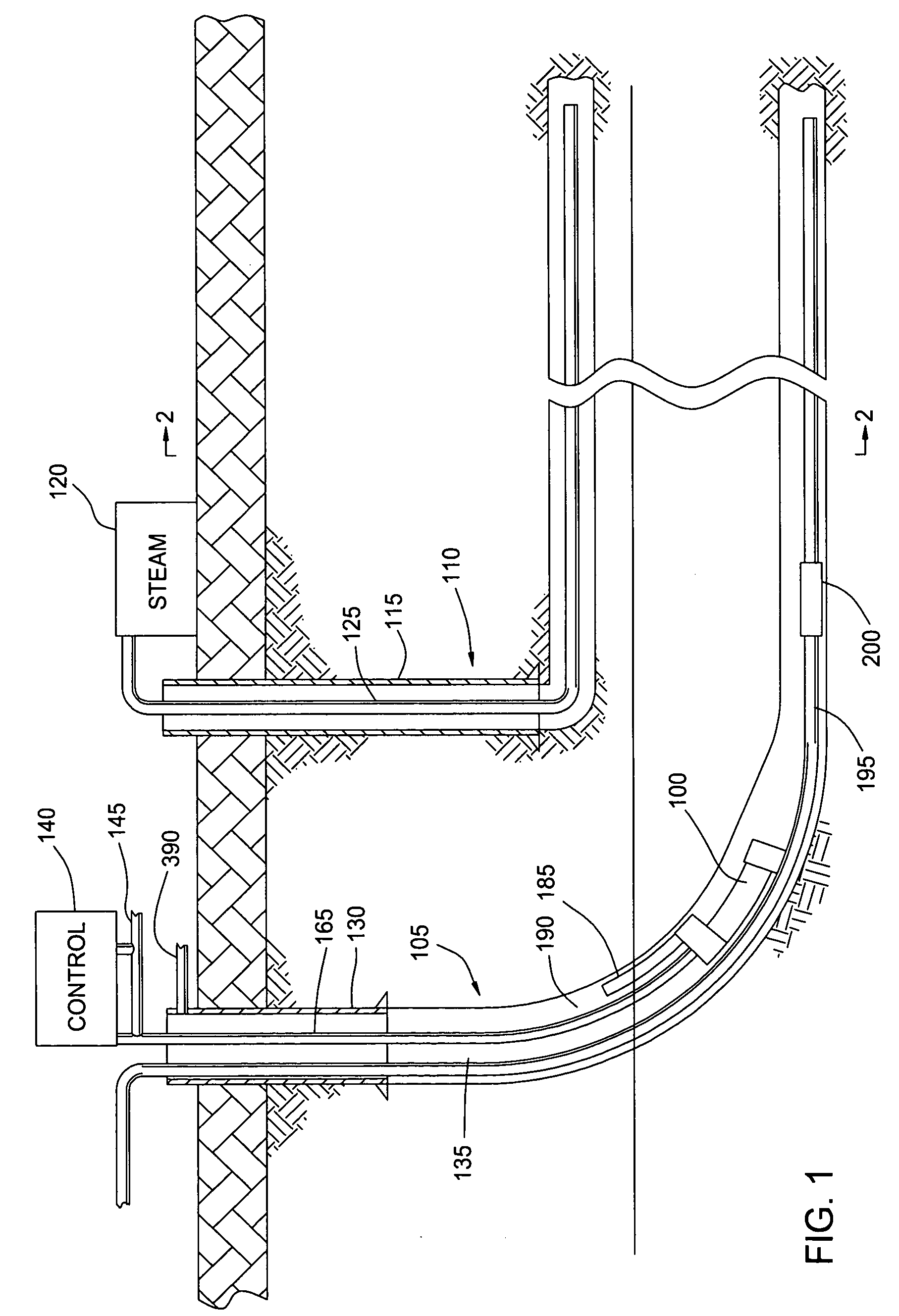
[0032] Embodiments of the present invention includes an apparatus and methods for producing hydrocarbon wells. FIG. 1 shows a partial cross-sectional view of a gas operated pump 100 disposed in a horizontal wellbore for use in a Steam Assisted Gravity Drainage (SAGD) operation. Although FIG. 1 illustrates the pump 100 for use in a SAGD operation, it should be understood that the pump 100 may be employed in many different completion operations such as in vertical or horizontal gas or petroleum wellbores, vertical or horizontal steam drive and vertical or horizontal cyclic steam drive. This invention utilizes high pressure gas as the power to drive the invention. It should be understood that gas refers to natural gas, steam, or any other form of gas. In a typical SAGD operation there are two coextensive horizontal wells, a lower well 105 and an upper injection well 110. As shown in FIG. 1, the upper injection well 110 includes casing 115 on the vertical portion of the wellbore. At the...


PUM


Abstract

Apparatus and methods for improving production from a wellbore are provided. In one embodiment, a downhole pump for use in a wellbore includes a chamber for accumulating formation fluids and a valve assembly for filling and venting gas to and from the chamber. In another embodiment, a gas operated pump for moving wellbore fluids in a wellbore includes a chamber for accumulating wellbore fluids, wherein the chamber in fluid communication with a production tubular and a surface mounted valve assembly in fluid communication with the chamber, wherein the valve assembly adapted to regulate gas flow to or from the chamber. In another embodiment, the valve assembly comprises a removable control valve disposed in a housing.

Description

CROSS-REFERENCE TO RELATED APPLICATIONS [0001] This application is a continuation-in-part of co-pending U.S. patent application Ser. No. 10 / 349,501, filed on Jan. 22, 2003, which application claims benefit of co-pending U.S. Provisional Patent Application Ser. No. 60 / 350,673, filed on Jan. 22, 2002, which applications are herein incorporated by reference in their entirety.BACKGROUND OF THE INVENTION [0002]1. Field of the Invention [0003] Apparatus and methods of the present invention relate to artificial lift for hydrocarbon wells. More particularly, the invention relates to gas operated pumps for operating a wellbore. More particularly still, the invention relates to a method and an apparatus for improving production from a wellbore. [0004] 2. Background of the Related Art [0005] Throughout the world there are major deposits of heavy oils which, until recently, have been substantially ignored as sources of petroleum since the oils contained therein were not recoverable using ordina...

Claims


Application Information

Patent Timeline
Patent Type & Authority Applications(United States)
IPC IPC(8): E21B43/00E21B43/12E21B43/24F04F1/08
CPCE21B43/12E21B43/129E21B43/2406E21B43/305F04F1/08
Inventor HOWARD, WILLIAM F.WILTSE, DARREN J.LANE, WILLIAM C.
Owner WEATHERFORD TECH HLDG LLC
Why Eureka
Try Eureka