Blood analyzer and method of separating plasma

a blood analyzer and plasma technology, applied in the field of chip-shaped blood analyzers, can solve the problems of unnecessarily increasing the amount of blood collected for clinical inspection, increasing the suction force or pump force, and unable to utilize the plasma on the upstream sid

Inactive Publication Date: 2006-04-20
JAPAN SCI & TECH CORP
View PDF4 Cites 21 Cited by
  • Summary
  • Abstract
  • Description
  • Claims
  • Application Information

AI Technical Summary

Problems solved by technology

Therefore, there has been a problem that the only plasma on the downstream side can be fed into the analysis means, and the plasma on the upstream side cannot be utilized.
This means that a blood-collecting amount necessary for clinical inspection is unnecessarily increased.
Since the blood cell fraction 311 sticks to the inner wall of the flow channel 303 a...

Method used


Image

  • Blood analyzer and method of separating plasma
  • Blood analyzer and method of separating plasma
  • Blood analyzer and method of separating plasma

Examples


first example

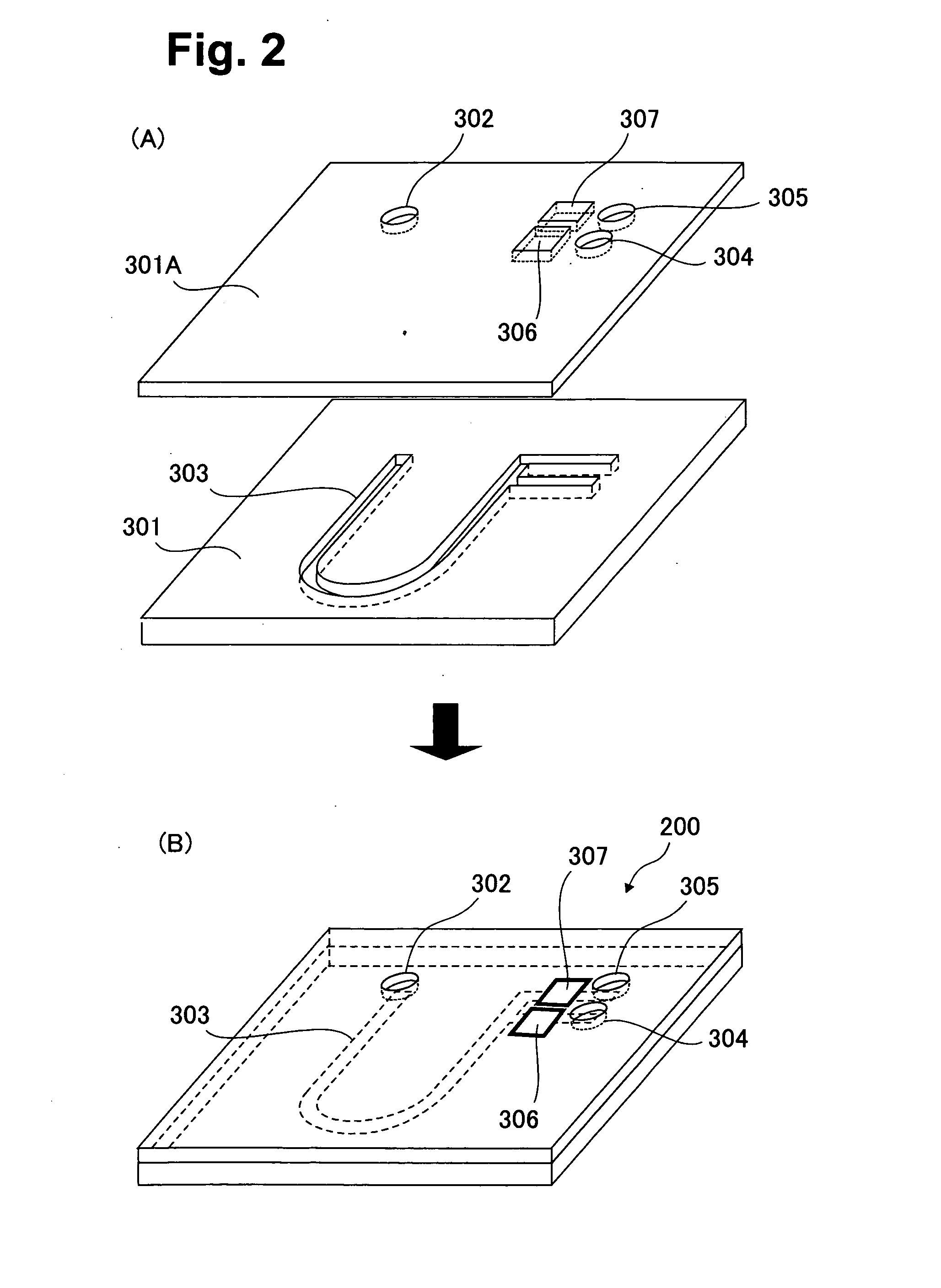
[0052] A blood analysis apparatus shown in FIG. 5 was prepared, a blood sample was introduced into the blood analysis apparatus to perform centrifugation, and thereafter the plasma fraction was, sucked. Additionally, one analysis means was disposed in the blood analysis apparatus for simplicity (see FIG. 8). In the blood analysis apparatus, two polyethylene terephthalate (PET) substrates having a thickness of 0.5 mm were provided, and the flow channel 303 was formed in one substrate by molding. In the other substrate, a blood inlet port 302 and a blood draw-in port (outlet port) 801 were formed. And an electrode formed of carbon paste which was coated with a hydrogen ion sensitive film was prepared and disposed as analysis means 802. FIG. 8 schematically shows dimensions of a blood analysis apparatus 210 and the flow channel 303 formed on the apparatus. A depth of all the flow channel was 100 μm.

[0053] 1 μL of human whole blood was introduced into the blood analysis apparatus 210 t...

second example

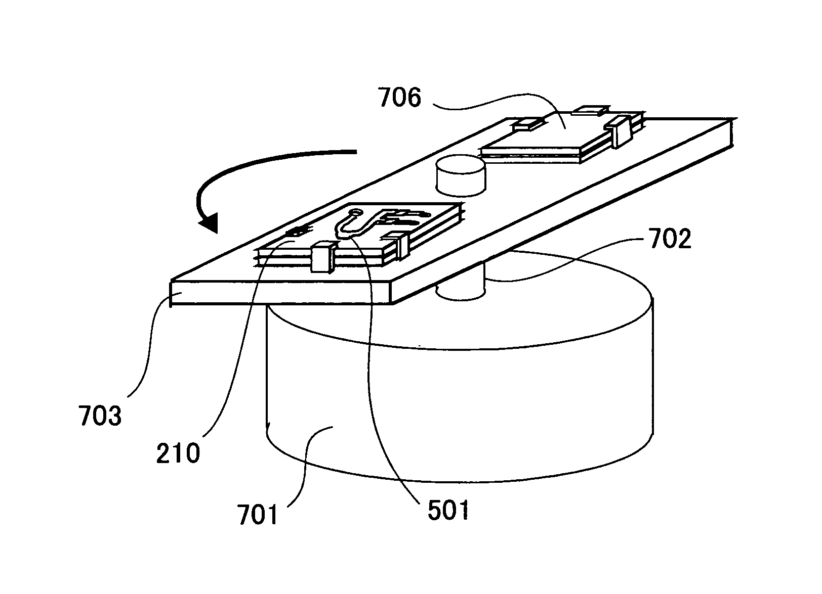
[0059] A blood analysis apparatus 220 having a blood cell reservoir 501A was prepared as shown in FIG. 9(A). Blood was introduced into the blood analysis apparatus to perform centrifugation, and thereafter a plasma fraction 602 was drawn in. It is to be noted that dimensions of the blood analysis apparatus and a flow channel design in this Example are substantially similar to those shown in FIG. 8. As shown in FIG. (9B), this blood analysis apparatus is different from that of FIG. 8 in that an area of an interface between the separated plasma 602 and a blood cell fraction 603 is reduced as compared with a blood analysis apparatus shown in FIG. 8, when the blood is introduced onto the blood analysis apparatus to perform the centrifugation. Accordingly, a draw-in force applied to the blood cell fraction when sucking the plasma is reduced, the surface of the blood cell fraction can be prevented from being disturbed and mixed with the plasma, and substantially all plasma is securely mov...

third example

[0061] As shown in FIG. 10(A), a flow channel width of a lower part of a U-shaped flow channel 303 was increased to constitute a blood cell reservoir 501B, and accordingly a blood analysis apparatus 230 was prepared. In the same manner as in the first and second examples, attempts were made to introduce blood, separate plasma from the blood cell fraction, and draw in plasma fraction. By centrifugation after the blood introduction, as shown in FIG. 10(B), plasma 602 and blood cell fraction 603 were separated, and the plasma fraction 602 only was drawn in without disturbing the blood cell fraction 603, and could be fed into analysis means 802. From the present example, it is seen that it is especially important that the plasma fraction should continuously exist without being divided by the blood cell fraction, when the blood is separated into the plasma and blood cell fractions by centrifugation. This also applies to the blood analysis apparatus having the blood cell reservoir midway ...


PUM


Abstract

In a blood analyzer for separating plasma in a flow channel by centrifugal operation, it is intended to effectively utilize a whole blood sample supplied into the flow channel, shorten the flow channel and reduce the apparatus size. It is also intended to reduce the amount of the blood to be collected, thereby reducing the burden on a subject. A blood cell reservoir wherein blood cells are precipitated is provided in a flow channel of a blood analyzer along the centrifugal direction upon centrifugation. Then blood cells are cumulated in the reservoir by centrifugation so that the plasma fraction is allowed to continuously exist in both of the upstream and downstream sides of the U-shaped flow channel without being divided by the blood cell fraction. Thus, the plasma in a required amount can be fed into the analysis means using a smaller amount of the whole blood. Therefore, the whole blood can be utilized more efficiently, which is suitable for the shortening of the flow channel and the reduction of the device size. The plasma, which is not divided by the blood cell fraction, can be transferred due to a lower negative suction pressure. Thus, the pump capacity required in drawing the plasma can be reduced, which contributes to the size reduction and cost down of peripheral devices.

Description

TECHNICAL FIELD [0001] The present invention relates to a chip-shaped blood analysis apparatus constituted by micro trench channels prepared in insulating substrates such as a quartz plate and a polymer resin plate. Particularly, the present invention relates to a plasma separation method for utilizing plasma fraction efficiently, when a small amount (several μL or less) of blood is introduced in a trench channels of the chip to perform centrifugal separation, the blood is separated into blood cell fraction and plasma fraction, and thereafter various chemical material concentrations in the plasma are measured, and a trench channel structure of the chip-shaped blood analysis apparatus. BACKGROUND ART [0002] In a conventional medical check-up or diagnosis of a disease state, several cc, a large amount of blood has heretofore been sampled from a patient, and analysis has been carried out by a large-scaled automatic blood analysis apparatus. Usually, this automatic analysis apparatus is...

Claims


Application Information

Patent Timeline
IPC IPC(8): G01N33/48G01N24/00B01L3/00B04B5/02G01N1/10G01N15/05G01N33/49G01N35/00
CPCB01L3/502753B01L2300/0816B01L2300/0864B01L2400/0409G01N15/05G01N33/491G01N2035/00495G01N33/49G01N1/10B04B5/02
Inventor OGAWA, HIROKIHORIIKE, YASUHIRO
Owner JAPAN SCI & TECH CORP
Why Eureka
Try Eureka