Monitoring of retinal temperature during laser therapy

a technology of laser therapy and retinal temperature, applied in the field of surgical and medical monitoring arts, can solve the problems of not being easily detected by medical personnel, affecting the treatment effect,

Inactive Publication Date: 2006-04-20
ROVATI LUIGI +1
View PDF9 Cites 14 Cited by
  • Summary
  • Abstract
  • Description
  • Claims
  • Application Information

AI Technical Summary

Problems solved by technology

Laser treatment allows closure of CNV; however some surrounding retinal tissue is also destroyed.
However, it is also a practical disadvantage, because smaller lesions produced by TTT are not readily detectable.
Hence, if retinal irradiance is insufficient to produce a therapeutic temperature increase, this may not be readily detected by medical personnel.
These approaches suffer from substantial inter-subject and intra-subject variability.
However the required instrumentation is expensive and may present risks to the patient.
However, these existing optical techniques typically do not provide a robust, accurate, and reliable determination of the end point of laser treatment that is suitable for use in conjunction with clinical laser eye treatment.
Yet another disadvantage is that precise calibration is required for each specific lens-transducer configuration.
This technique does not directly measure retinal temperature, but rather detects morphological changes induced in response to the interaction of ocular tissue with the laser beam.
This technique also does not directly measure retinal temperature, but rather measures topological tissue changes during tissue heating.
Such topological changes are expected to be small, however, and moreover correlating such dimensional changes with retinal temperature may be difficult.
Strong spectral changes of the backscattered light with temperature were observed for temperature changes of around 25-50° C. This method may be susceptible to inter-subject variability induced by differences in pigmentation between subjects.

Method used


Image

  • Monitoring of retinal temperature during laser therapy
  • Monitoring of retinal temperature during laser therapy
  • Monitoring of retinal temperature during laser therapy

Examples


Embodiment Construction

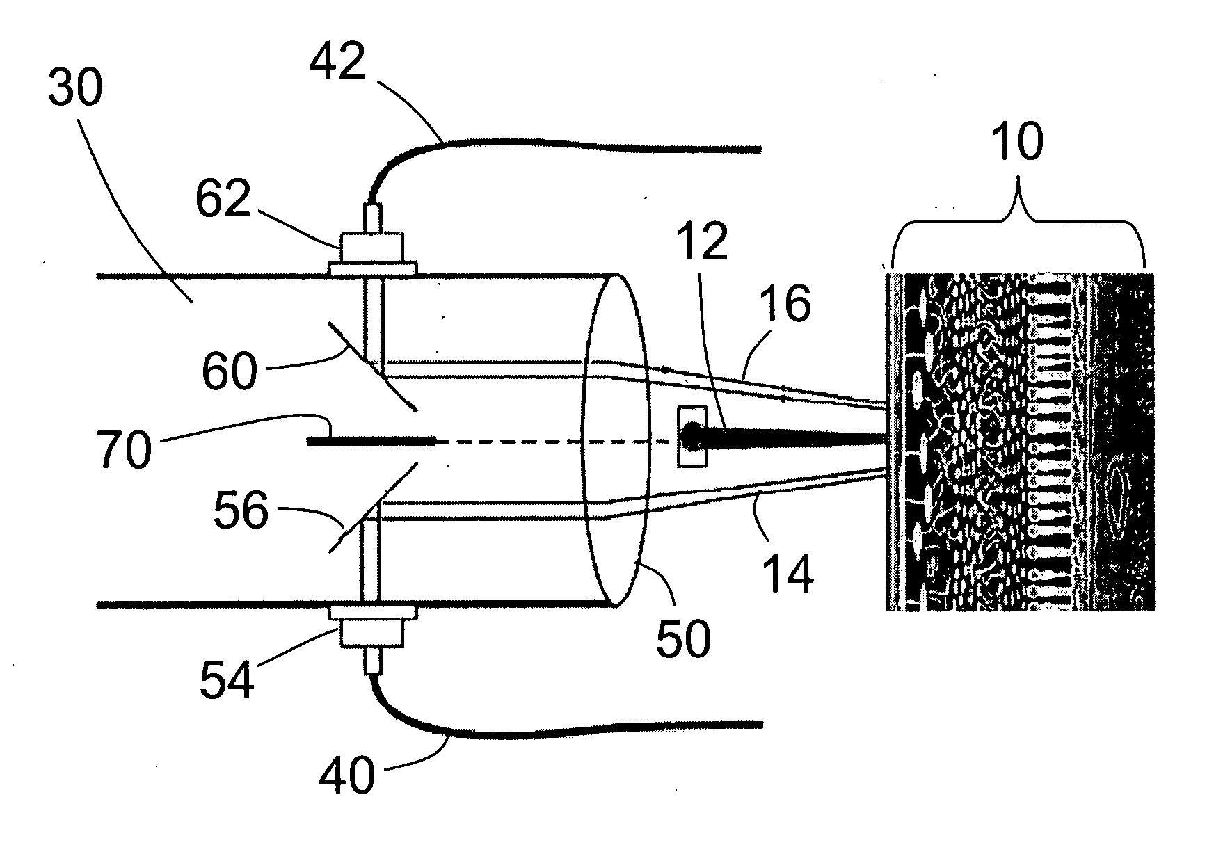
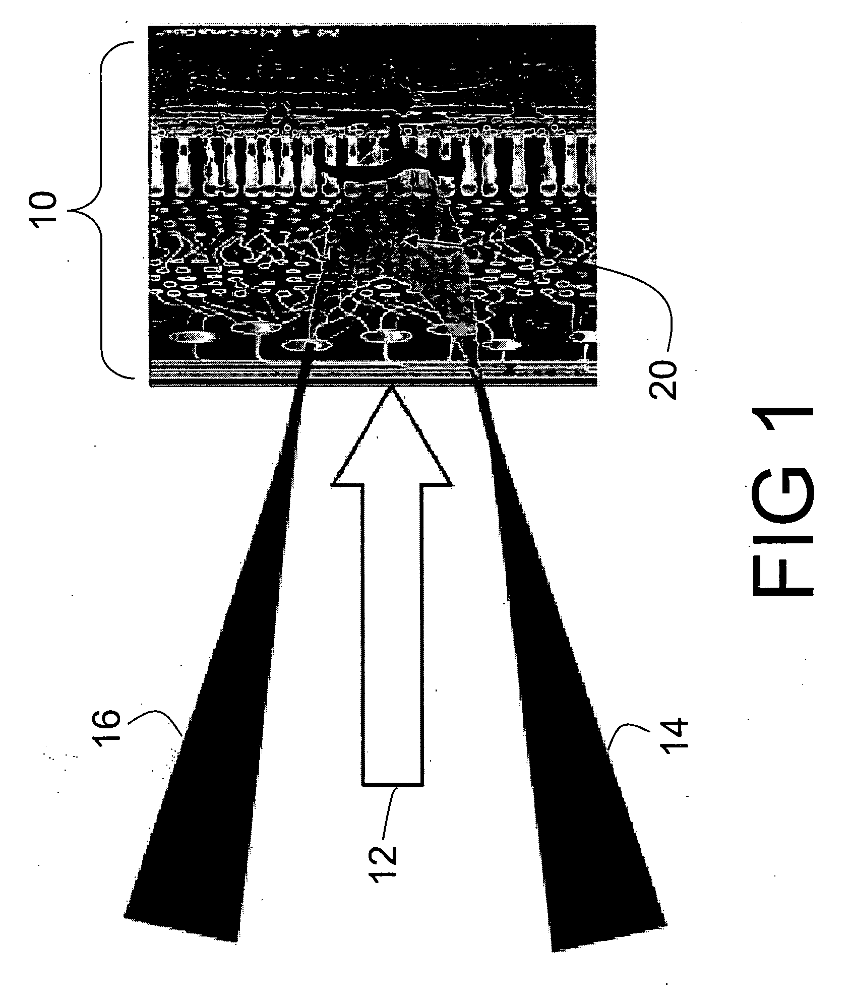
[0028] With reference to FIG. 1, the optical techniques disclosed herein exploit temporal fluctuation of secondary emitted photons from the irradiated tissue to measure the tissue temperature. Retinal tissue 10 is treated using a treatment laser beam 12. The tissue is also illuminated by a low power probe beam 14 illuminating the retinal tissue 10 at an angle respective to the treatment laser beam 12. In some embodiments, the probe beam 14 is a focused laser beam; however, focused lamp light, focused light from a semiconductor light emitting diode (LED) or laser, or the like can also be used. Interaction of the probe beam 14 with the retinal tissue 10 produces a secondary beam 16 of light that is collected angularly symmetrically with respect to the treatment laser beam 12. The temperature of the treated retinal region 10 is determined by analyzing the scattering properties of a zone 20 included within the probe beam 14 and from which the secondary radiation 16 is emitted. In some c...


PUM


Abstract

In a laser eye treatment apparatus, a probe light source generates a secondary emitted light emanating from a treatment area of retinal tissue that is irradiated by a treatment light source. An optical detector detects the secondary emitted light. A processor statistically analyzes the secondary emitted light to determine a temperature of the treatment area of retinal tissue.

Description

BACKGROUND [0001] This application claims the benefit of U.S. Provisional Application No. 60 / 587,758, filed Jul. 14, 2004. U.S. Provisional Application No. 60 / 587,758 is incorporated by reference herein in its entirety.[0002] The following relates to the surgical and medical monitoring arts. It especially relates to monitoring of retinal temperature during laser eye surgery, and will be described with particular reference thereto. However, the invention will also find application in conjunction with other optical surgical procedures and in the monitoring of ocular tissue temperature during various ocular medical procedures and clinical ophthalmology studies. [0003] A long-felt need in laser eye therapy is the ability to monitor the temperature of the irradiated tissue during the laser procedure. In ophthalmology laser therapy is used to treat a number of different ocular tissues and ocular pathologies, including retinal tissue and diseases. Age-related macular degeneration, which is...

Claims


Application Information

Patent Timeline
Patent Type & Authority Applications(United States)
IPC IPC(8): A61B18/18A61B5/00
CPCA61B2017/00057A61B2017/00084A61F9/008A61F9/00821A61F2009/00844A61F2009/00857A61F2009/00863A61F2009/00878
Inventor ROVATI, LUIGISTAURENGHI, GIOVANNI
Owner ROVATI LUIGI
Why Eureka
Try Eureka