Thin film thermoelectric devices for hot-spot thermal management in microprocessors and other electronics

a technology of thermoelectric devices and microprocessors, applied in the direction of machines, lighting and heating apparatus, domestic cooling apparatus, etc., can solve the problems of increasing the heat load dissipation affecting the efficiency of heat dissipation, so as to reduce the total heat load and improve the efficiency of thermoelectric devices

Active Publication Date: 2006-04-27
LAIRD THERMAL SYST INC
View PDF98 Cites 166 Cited by
  • Summary
  • Abstract
  • Description
  • Claims
  • Application Information

AI Technical Summary

Benefits of technology

[0012] Another object of the present invention is to utilize a thermoelectric device structure in which the thermoelectric properties of the device are not contravened by inadvertent heat flux from the hot side of the integrated thermoelectric device to the heat-dissipating integrated circuit device.
[0013] Still another object of the present invention is to provide a thermoelectric device in which high ZT thermoelectric materials are used to improve the efficiency of the thermoelectric device and thus reduce the total heat load dissipated from the integrated circuit device to the outside environment.
[0014] Another object of the present invention is to provide a thermoelectric device structure and method in which the operating temperature of a heat-dissipating integrated circuit device coupled thereto is reduced from where the temperature would be had the heat-dissipating integrated circuit device merely been directly coupled to a passive heat-spreader.

Problems solved by technology

With large amounts of heat being generated, the problem of efficient heat dissipation has become more acute.
Further, the increased density of chips produces problems due to local heating and thermally induced stress which can deteriorate chip performance and longevity.
In addition to heating problems with high-density circuits, supplying power to the enormous number of devices as well as power management are also becoming major issues.
Indeed, it is well known that passive cooling devices have a limited capacity to dissipate heat unless the passive cooling devices use microchannels which in turn require high fluid pressures
Yet, these approaches are limited in their performance due to the thermoelectric material characteristics of the thermoelements in the TE devices by the profile of the devices such that the thermoelectric devices provided only limited cooling power densities (such as 1 to 2 W / cm2) compared to the present invention which can provide cooling power densities in the range of 10 to 1000 W / cm2, by the system design which attempted to adapt a macroscopic TE technology to cool microscopic IC devices, or by the lack of the HAF-LIOF concepts that were discussed in the U.S. Provisional Application No. 60 / 528,479.

Method used


Image

  • Thin film thermoelectric devices for hot-spot thermal management in microprocessors and other electronics
  • Thin film thermoelectric devices for hot-spot thermal management in microprocessors and other electronics
  • Thin film thermoelectric devices for hot-spot thermal management in microprocessors and other electronics

Examples


Embodiment Construction

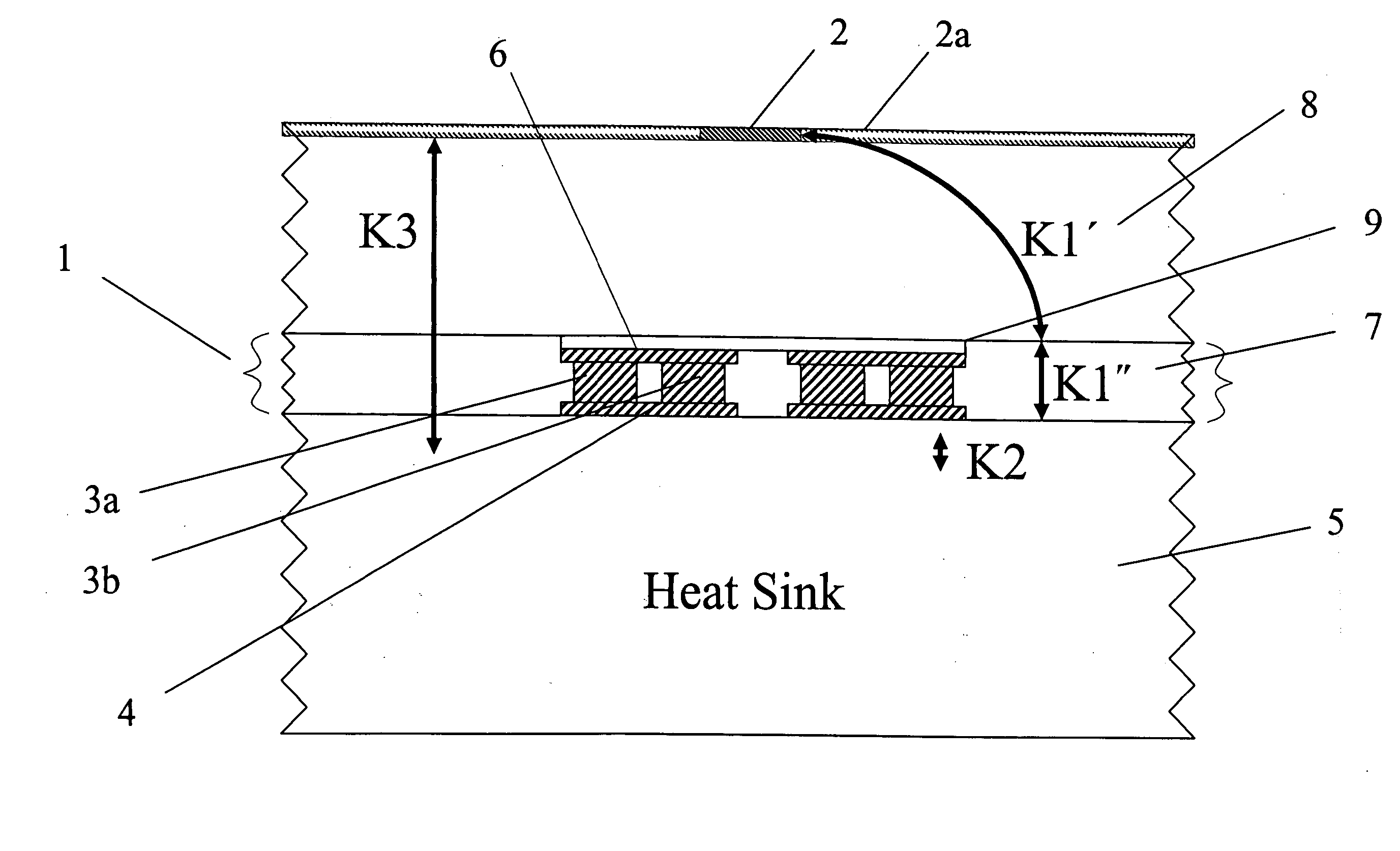
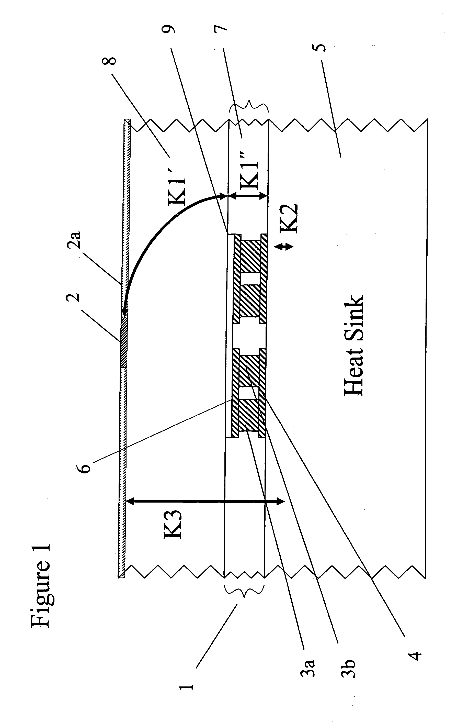
[0038] Referring now to the drawings, wherein like reference numerals designate identical, or corresponding parts throughout the several views, and more particularly to FIG. 1 thereof, FIG. 1 depicts a schematic of one embodiment of a thermoelectric device structure according to the present invention. As shown in FIG. 1, a thermoelectric device structure 1 of the present invention is coupled to a heat-generating device 2a such as, for example, an integrated circuit chip contained in the medium 8. For example, integrated circuit devices requiring cooling of hot spots 2 include microprocessors, graphic processors and other heat-generating devices fabricated in mediums 8 such as for example silicon, germanium, silicon-germanium, gallium arsenide, or any such semiconductor material. The thermoelectric device structure 1 of the present invention permits the temperature of the hot spot 2 of the heat-generating device 2a to be reduced such as, for example, by 5° C. relative to a temperatur...


PUM


Abstract

A structure, system and method for controlling a temperature of a heat generating device in a solid medium, wherein heat is extracted from the medium into at least one heat extraction device, the heat extraction device dissipates heat into an environment apart from the medium by a heat sink thermally coupled to the heat extraction device; and heat from the medium is dissipated into the heat sink by a first thermal interface material thermally coupling the heat sink to the medium.

Description

CROSS-REFERENCE TO RELATED DOCUMENTS [0001] This application is related to U.S. Provisional Application No. 60 / 372,139 entitled “Thermoelectric device technology utilizing double-sided Peltier junctions” filed on Apr. 15, 2002, the entire contents of which is incorporated herein by reference. This application is related to U.S. Pat. No. 6,300,150 entitled “Thin-film thermoelectric device and fabrication method of same” issued Oct. 9, 2001, the entire contents of which is incorporated herein by reference. This application is related to U.S. Pat. No. 6,071,351 entitled “Low temperature chemical vapor depositor and etching apparatus and method” issued Jun. 6, 2002, the entire contents of which is incorporated herein by reference. This application is related to U.S. Pat. No. 6,505,468 entitled “Cascade cryogenic thermoelectric cooler for cryogenic and room temperature applications” issued Jan. 14, 2003, the entire contents of which is incorporated herein by reference. This application i...

Claims


Application Information

Patent Timeline
Patent Type & Authority Applications(United States)
IPC IPC(8): F25B21/02F25D23/12
CPCF25B21/02F25B2321/003H01L35/30H01L2924/0002H01L2924/00H10N10/13
Inventor VENKATASUBRAMANIAN, RAMAALLEY, RANDALL G.ADDEPALLI, PRATIMAREDDY, ANIL J.SIIVOLA, EDWARD P.O'QUINN, BROOKS C.COONLEY, KIP D.POSTHILL, JOHNCOLPITTS, THOMAS
Owner LAIRD THERMAL SYST INC
Why Eureka
Try Eureka