Vascular conduit device and system for implanting

a technology of vascular conduits and fluid conduits, applied in the field of devices and methods for creating and maintaining fluid conduits, can solve the problems of valve replacement, poorly accepted aac insertion procedures, and inability to achieve the same degree of technical simplicity as aac insertion operations, so as to improve the ease and safety of vascular conduit insertion

Active Publication Date: 2006-04-27
GEORGIA TECH RES CORP +1
View PDF29 Cites 94 Cited by
  • Summary
  • Abstract
  • Description
  • Claims
  • Application Information

AI Technical Summary

Benefits of technology

[0016] Use of this new vascular conduit device, system, and method will significantly improve the ease and safety of vascular conduit insertion (such as the implanta

Problems solved by technology

However, the AAC insertion procedure has been poorly accepted, primarily because of early valve failures using first-generation bioprostheses as well as the success of direct LVOTO repair and aortic valve replacement.
Further, the AAC insertion operation, with or without cardiopulmonary bypass, has not been as technically straightforward as direct aortic valve replacement.
While off-pump cases h

Method used


Image

  • Vascular conduit device and system for implanting
  • Vascular conduit device and system for implanting
  • Vascular conduit device and system for implanting

Examples


first embodiment

[0056] A ventricular coring device 830 may then be threaded in-line over the hemostatic device 820 and a core of ventricular muscle is removed from the tissue wall 850 of the apex in order to form an aperture 800. In addition to known coring techniques, an annular contact laser (and in some embodiments a “cool” cutting pulsed excimer laser, having elements arranged in a circular array 835) may be used to vaporize the tissue along the perimeter of the core. The cored tissue may then be removed according to known methods. According to a further alternative embodiment, a contact laser may be used to vaporize the entire area of the core, eliminating the need to remove cored tissue. In yet another embodiment, a mechanical coring device (such as a catheter-based rotoblator device) or an ultrasonic coring device, may be used to form the aperture 800. No matter the method of coring, once coring has been-completed, the coring device 830 may be removed while the occlusion device maintains hem...

second embodiment

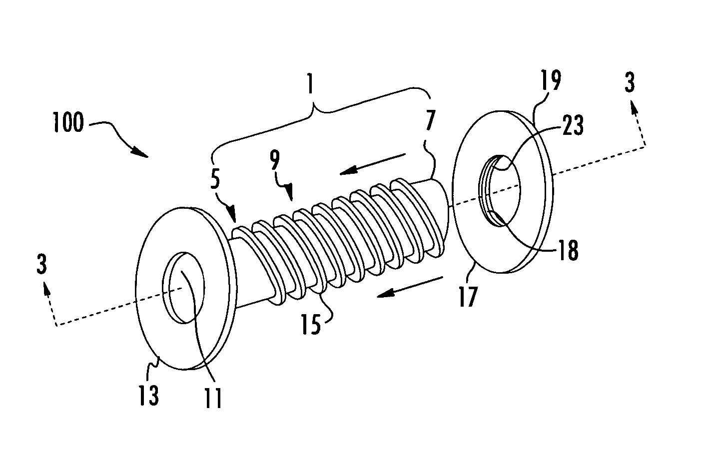
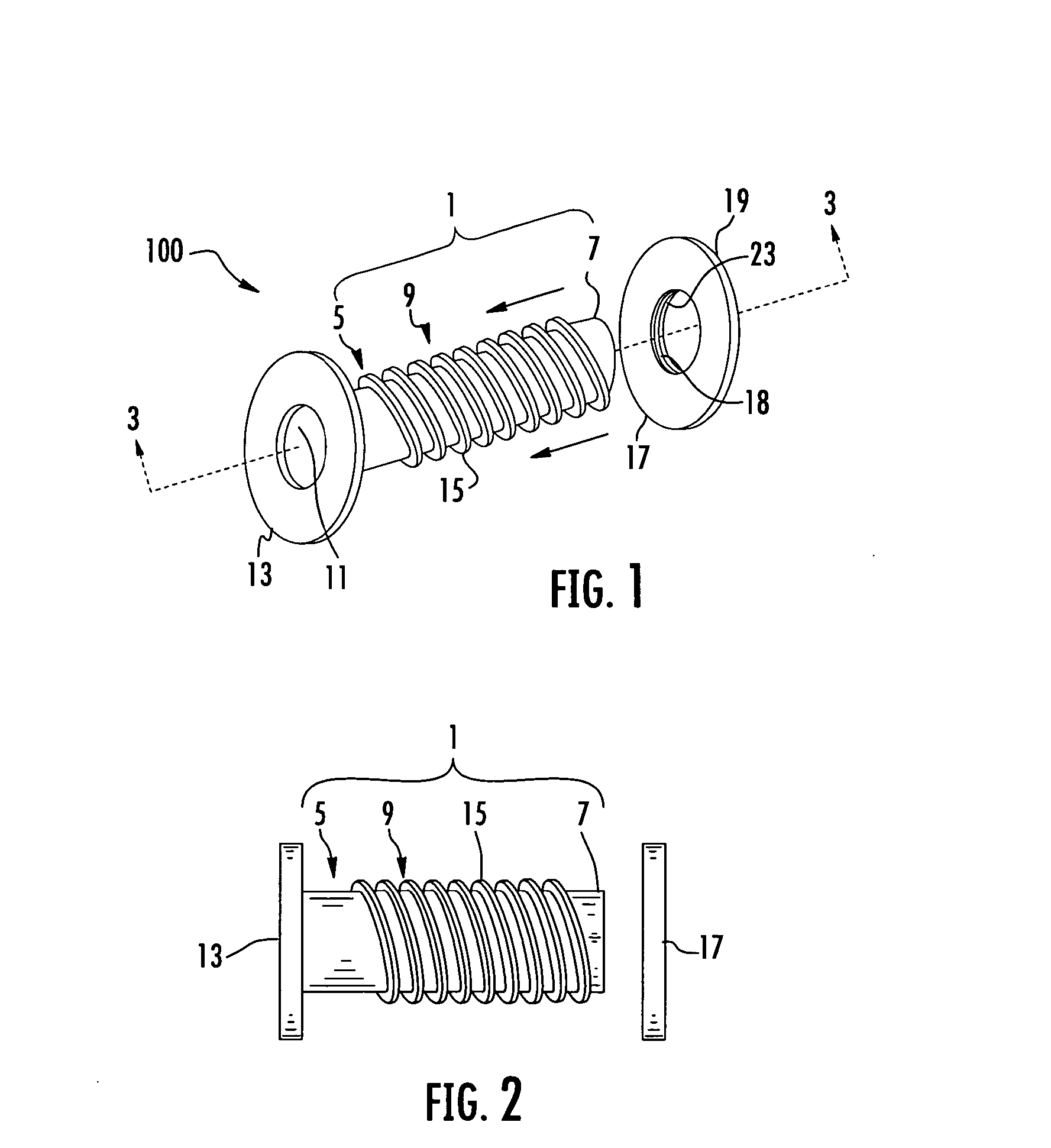
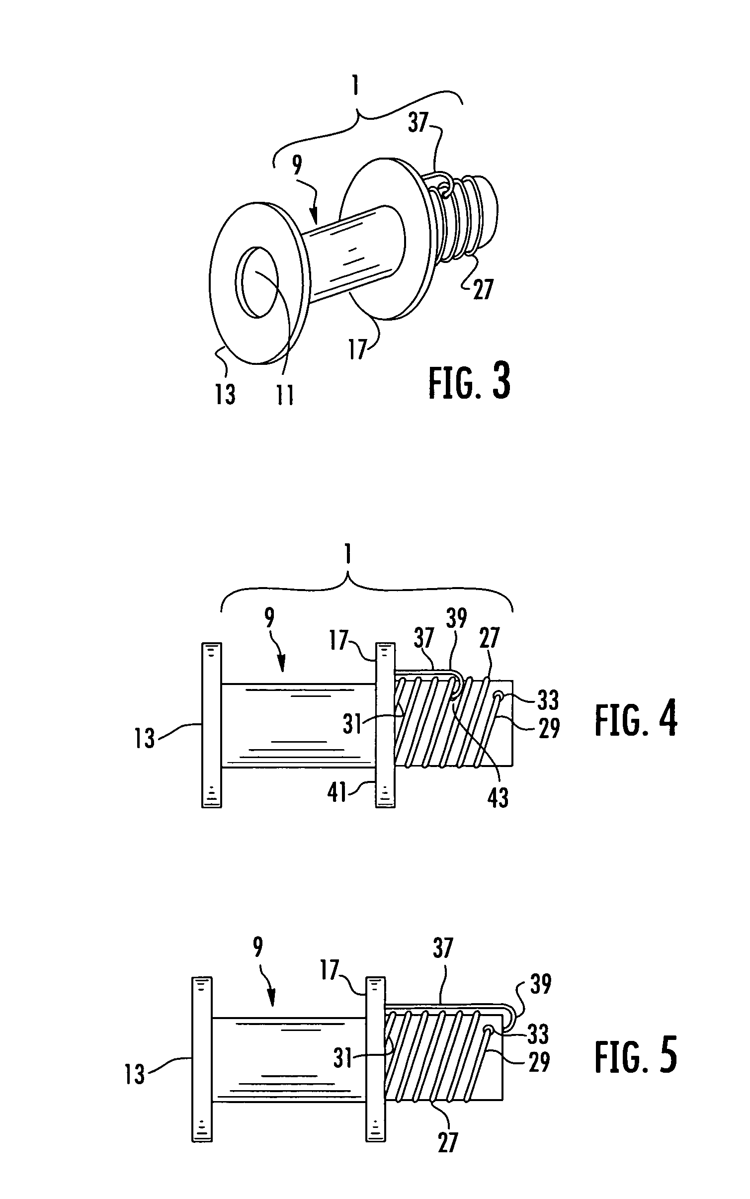
[0057] According to it second embodiment, once the flexible flange 13 has been introduced into the ventricle and pulled back to engage the first tissue surface 853, release-device 37 is released, allowing biasing device 27 to force the external ring 17 against the second tissue surface 855 of the ventricular apex. According to a further aspect of this embodiment of the invention, threads on the inside diameter of external ring 17 may be made to engage threads on the outer surface of the tube 1 to further secure external ring 17 against the tissue wall 850 of the ventricular apex.

[0058] Once the vascular conduit device 100 is firmly in place (see generally FIG. 8B), the occlusion device 820 may be retracted and withdrawn. The vascular conduit device 100 may then be clamped shut and / or capped while its free end (defined by the proximal end 7 of the tube 1) is connected to a valved conduit and / or graft which may terminate at a complementary vascular conduit device 100 implanted in the ...


PUM


Abstract

The present invention provides a vascular conduit device including a deformable flange and complementary securing ring in cooperation for securing the device within an aperture defined in a tissue wall. The present invention further provides a system for implanting such a vascular conduit device in a tissue wall. More specifically, the present invention provides a system including a coring device for defining an aperture in a tissue wall (such as a ventricle and/or a blood vessel) and securely implanting a vascular conduit device therein so as to provide fluid communication between a first and second surface of the tissue wall via the vascular conduit device.

Description

CROSS-REFERENCE TO RELATED APPLICATIONS [0001] This application is a continuation-in-part of copending U.S. patent application Ser. No. 10 / 915,691, filed on Aug. 11, 2004, which is hereby incorporated herein in its entirety by reference.FIELD OF INVENTION [0002] This invention relates to devices and methods for creating and maintaining a fluid conduit in a tissue wall. For example, some embodiments of the present invention may provide an alternative conduit between the left ventricle and the aorta to create a double-outlet left ventricle. BACKGROUND OF THE INVENTION [0003] Construction of an alternative conduit between the left ventricle and the aorta (an apicoaortic conduit, or AAC) to create a double-outlet left ventricle (LV) has been successfully employed to treat a variety of complex congenital LV outflow obstruction (fibrous tunnel obstruction, aortic annular hypoplasia, tubular hypoplasia of the ascending aorta, and patients with diffuse septal thickening, severe LV hypertrop...

Claims


Application Information

Patent Timeline
IPC IPC(8): A61F2/06
CPCA61B17/11A61B2017/00243A61B2017/00252A61B2017/1107A61B2017/1135A61F2/064A61F2/2493A61F2/06A61M27/002
Inventor VASSILIADES, THOMAS A.YOGANATHAN, AJITJIMENEZ, JORGE HERNAN
Owner GEORGIA TECH RES CORP
Why Eureka
Try Eureka