EUV collector debris management

a technology of debris management and collector, applied in the direction of electrostatic cleaning, cleaning process and apparatus, chemical apparatus and processes, etc., can solve the problems of dpp or lpp perception of inability to remove tin from optical elements, and achieve the effect of reducing the optical performance of materials and reducing the reflectivity of reflective surfaces

Inactive Publication Date: 2006-05-04
ASML NETHERLANDS BV
View PDF86 Cites 87 Cited by
  • Summary
  • Abstract
  • Description
  • Claims
  • Application Information

AI Technical Summary

Benefits of technology

[0006] A method and apparatus are disclosed that may comprise an EUV light producing mechanism utilizing an EUV plasma source material comprising a material that will form an etching compound, which plasma source material produces EUV light in a band around a selected center wavelength comprising: an EUV plasma generation chamber; an EUV light collector contained within the chamber having a reflective surface containing at least one layer comprising a material that does not form an etching compound and / or forms a compound layer that does not significantly reduce the reflectivity of the reflective surface in the band; an etchant source gas contained within the chamber comprising an etchant source material with which the plasma source material forms an etching compound, which etching compound has a vapor pressure that will allow etching of the etching compound from the reflective surface. The etchant source material may comprises a halogen or halogen compound. The etchant source material may be selected based upon the etching being stimulated in the presence of photons of EUV light and / or DUV light and / or any excited energetic photons with sufficient energy to stimulate the etching of the plasma source material. The apparatus may further comprise an etching stimulation plasma generator providing an etching stimulation plasma in the working vicinity of the reflective surface; and the etchant source material may be selected based upon the etching being stimulated by an etching stimulation plasma. There may also be an ion accelerator accelerating ions toward the reflective surface. The ions may comprise etchant source material. The apparatus and method may comprise an EUV light producing mechanism utilizing an EUV plasma source material comprising a material that will form an etching compound, which plasma source material produces EUV light in a band around a selected center wavelength which may comprise an EUV plasma generation chamber; a subsystem opening in the chamber comprising an optical element within the subsystem opening exposed to EUV, comprising a material that does not form an etching compound and / or forms a compound layer that does not significantly reduce the optical performance of the material; an etchant source gas contained in operative contact with the optical element comprising an etchant source material with which the plasma source material forms an etching compound, which etching compound has a vapor pressure that will allow etching of the etching compound from the optical element. The etchant source material and related gases may be as described above.

Problems solved by technology

A problem with tin in such applications has been the removal of plasma produced debris from optical surfaces in the EUV light source production chamber.
One of the troubling aspects of tin as a target according to the art is the perceived inability to remove tin from optical elements critical to the operation of the DPP or LPP apparatus for producing EUV light, e.g., the primary collector mirror in either a DPP or LPP system, or from such optics as windows used, e.g., for metrology and / or lenses used for, e.g., metrology and / or focusing or directing of the laser light pulses to the plasma initiation site for LPP.

Method used


Image

  • EUV collector debris management
  • EUV collector debris management
  • EUV collector debris management

Examples


Embodiment Construction

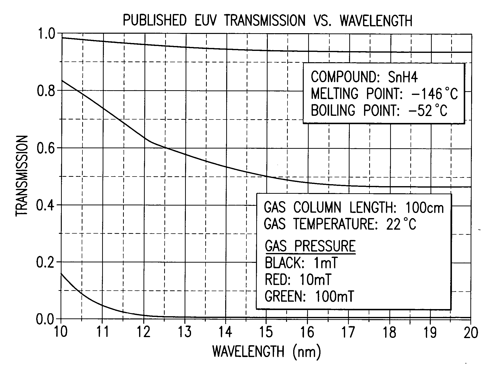
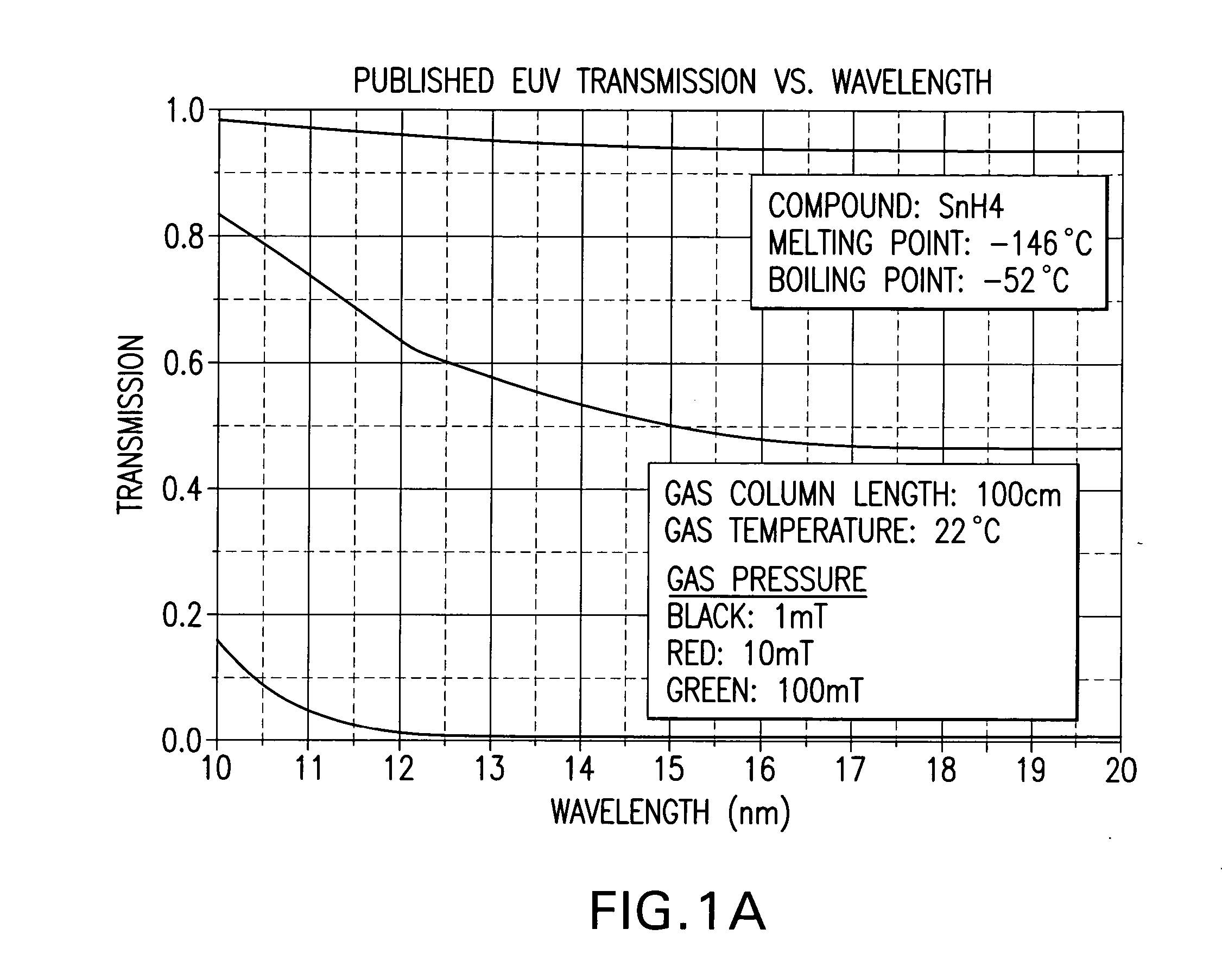
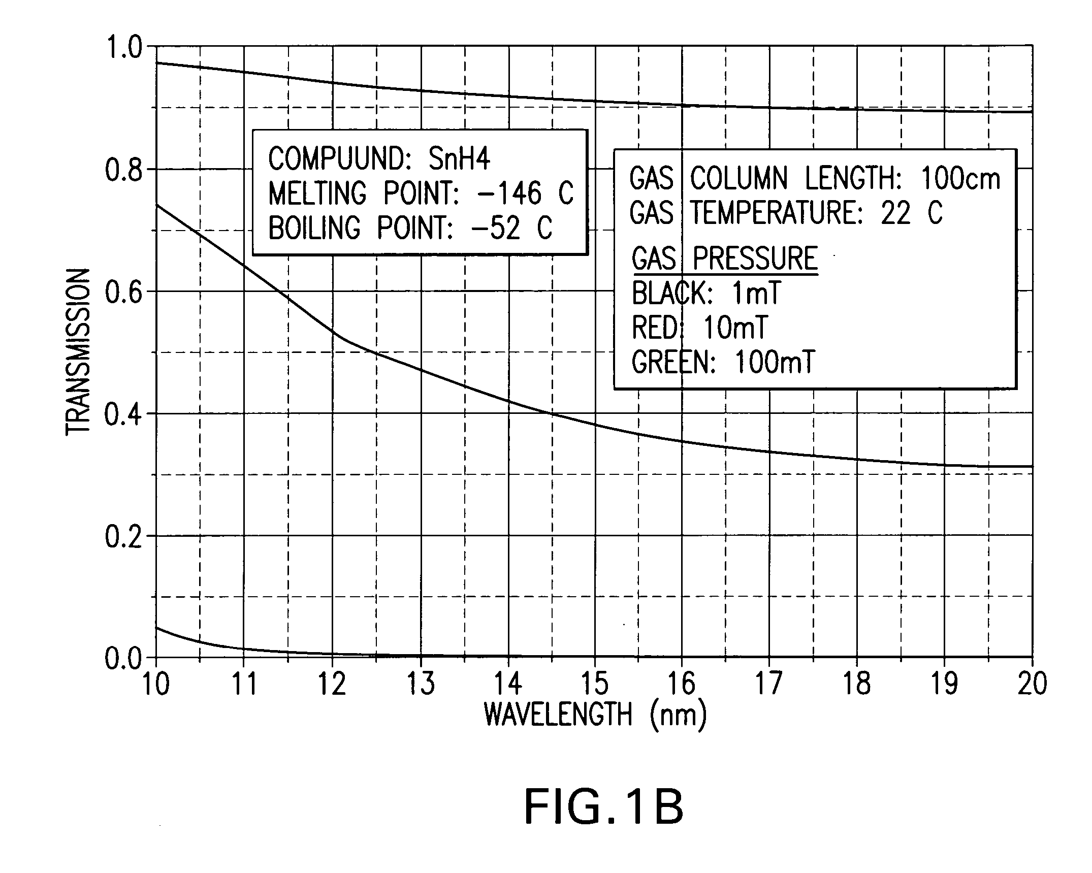
[0013] At least one tin hydride investigated by applicants, e.g., SnH4 has a large vapor pressure at temperatures at or below 450-500° C. and an activation energy to form the compound from a tin halogen (hydrogen) reaction is high and thus requires a large amount of power applied to the mirror surface for formation. Applicants have considered other possible halogen forming compounds (halides and hydrides) made from EUV target materials currently under consideration, e.g., tin.

[0014] Some relevant values are shown below in Table I.

TABLE ICompoundMelting Point (° C.)Boiling Point (° C.)SnH4−146−52SnF2213850SnF4—705SnCl2247623SnCl4−33114SnBr2216620SnBr431202SnI2320714SnI4143364H2−259−252F2−219−188Cl2−101−34Br2−7359I2113184Xe−111−108

[0015] The above noted Phillips patent application contains plots of pressure vs. temperature for most of these compounds and shows that most have higher vapor pressure at any given temperature than lithium (lithium's boiling point is 1342° C.).

[0016] Ap...


PUM

PropertyMeasurementUnit
temperaturesaaaaaaaaaa
boiling pointaaaaaaaaaa
radiiaaaaaaaaaa

Abstract

A method and apparatus that may comprise an EUV light producing mechanism utilizing an EUV plasma source material comprising a material that will form an etching compound, which plasma source material produces EUV light in a band around a selected center wavelength comprising: an EUV plasma generation chamber; an EUV light collector contained within the chamber having a reflective surface containing at least one layer comprising a material that does not form an etching compound and/or forms a compound layer that does not significantly reduce the reflectivity of the reflective surface in the band; an etchant source gas contained within the chamber comprising an etchant source material with which the plasma source material forms an etching compound, which etching compound has a vapor pressure that will allow etching of the etching compound from the reflective surface. The etchant source material may comprises a halogen or halogen compound. The etchant source material may be selected based upon the etching being stimulated in the presence of photons of EUV light and/or DUV light and/or any excited energetic photons with sufficient energy to stimulate the etching of the plasma source material. The apparatus may further comprise an etching stimulation plasma generator providing an etching stimulation plasma in the working vicinity of the reflective surface; and the etchant source material may be selected based upon the etching being stimulated by an etching stimulation plasma. There may also be an ion accelerator accelerating ions toward the reflective surface. The ions may comprise etchant source material. The apparatus and method may comprise a part of an EUV production subsystem with an optical element to be etched of plasma source material.

Description

RELATED APPLICATIONS [0001] This application is related to U.S. patent applications Ser. No. 10 / 409,254, entitled EXTREME ULTRAVIOLET LIGHT SOURCE, filed on Apr. 8, 2003, Attorney Docket No. 2002-0030-01, and Ser. No. 10 / 798,740, entitled COLLECTOR FOR EUV LIGHT SOURCE, filed on Mar. 10, 2004, Attorney Docket No. 2003-0083-01, and Ser. No. 10 / 615,321, entitled A DENSE PLASMA FOCUS RADIATION SOURCE, filed on Jul. 7, 2003, Attorney docket No. 2003-0004-01, and Ser. No. 10 / 742,233, entitled DISCHARGE PRODUCED PLASMA EUV LIGHT SOURCE, filed on Dec. 18, 2003, Attorney docket No. 2003-0099-01, and Ser. No. 10 / 803,526, entitled A HIGH REPETITION RATE LASER PRODUCED PLASMA EUV LIGHT SOURCE, filed on Mar. 17, 2004, Attorney docket No. 2003-0125-01, and, entitled A DENSE PLASMA FOCUS RADIATION SOURCE, filed on May 21, 2003, Attorney Docket No. 2003-0132-01, and Ser. No. 10 / 900,836, entitled EUV LIGHT SOURCE, filed on Jul. 27, 2004, Attorney docket No. 2004-0044-01, all co-pending and assigned...

Claims


Application Information

Patent Timeline
Patent Type & Authority Applications(United States)
IPC IPC(8): H01L21/306B08B6/00B44C1/22
CPCB08B7/00H01L21/306
Inventor PARTLO, WILLIAM N.SANDSTROM, RICHARD L.FOMENKOV, IGOR V.ERSHOV, ALEXANDER I.OLDHAM, WILLIAMMARX, WILLIAM F.HEMBERG, OSCAR
Owner ASML NETHERLANDS BV
Why Eureka
Try Eureka