Light emitting device with a thermal insulating and refractive index matching material

a technology of refractive index matching and light emitting device, which is applied in the direction of discharge tube luminescnet screen, discharge tube/lamp details, electric discharge lamps, etc., can solve the problems of poor thermal stability of phosphors, performance degradation, and light conversion efficiency can decline, so as to reduce heat conduction and increase the light generating efficiency of the light emitting device

Active Publication Date: 2006-05-04
LED ENGIN
View PDF73 Cites 151 Cited by
  • Summary
  • Abstract
  • Description
  • Claims
  • Application Information

AI Technical Summary

Benefits of technology

[0023] The use of a thermal insulating material reduces heat conduction from the LED to the phosphor and thus protects the phosphor from thermal degradation. Furthermore, choosing a thermal insulating material that has a higher refractive index also results in a closer match between the refractive index of the thermal insulating material and the refractive index of the LED materials. This helps to increase the light generating efficiency of the light emitting device.

Problems solved by technology

One problem with LED-based white light sources described above is the poor thermal stability of the phosphors.
Specifically, exposure to high temperatures for extended periods tends to alter the chemical and physical properties of such phosphors causing performance deterioration.
For instance, the light conversion efficiency can decline and the wavelength of output light can shift, both altering the balance of the light mixture and potentially diminishing the intensity of the overall output.
Other problems commonly found with LED-based white light sources are transient color changes and uneven color distributions, both caused by temperature gradients in the phosphor-containing material.
Such behaviors often create an unsatisfactory illumination.
Specifically, internal reflection at the LED / encapsulant interface prevents a fraction of the light generated inside the LED from escaping and can significantly reduce the light efficiency of the device (Lumens per Watt).
With such high power outputs, devices incorporating such LEDs can run very hot.
The above-mentioned thermal problems worsen with increasing temperature and therefore are particularly severe for devices that incorporate high-power LEDs with phosphors.
Presently, the above-mentioned thermal problems have severely limited the allowable LED temperature to only about 125° C. and have limited the allowable thermal resistance of prior art lighting systems.

Method used


Image

  • Light emitting device with a thermal insulating and refractive index matching material
  • Light emitting device with a thermal insulating and refractive index matching material
  • Light emitting device with a thermal insulating and refractive index matching material

Examples


Embodiment Construction

[0031] The present disclosure provides a light emitting device using a light emitting diode (LED) and a phosphor thermally insulated from the LED. Those skilled in the art will recognize that various features disclosed in connection with the embodiments may be used either individually or jointly. It is to be appreciated that while the present inventions have been described with reference to preferred implementations, those having ordinary skill in the art will recognize that the present inventions may be beneficially utilized in any number of environments and implementations.

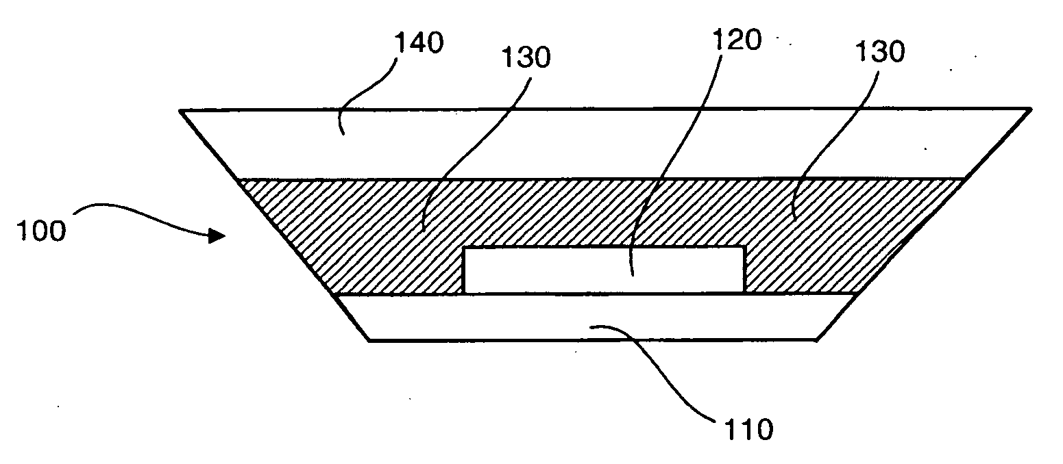
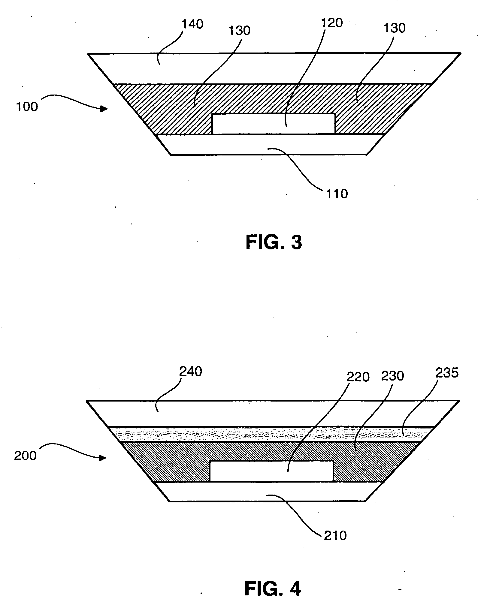
[0032]FIG. 3 is a schematic diagram of a light emitting device 100 in accordance with an embodiment of the present invention. From bottom to top, the light emitting device 100 comprises a substrate 110, an LED 120 having a bottom side mounted to the substrate 110, an encapsulant member 130 disposed over a top surface of the LED 120, and an optional auxiliary member 140 disposed over the encapsulant member 130, ...


PUM

PropertyMeasurementUnit
glass transition temperatureaaaaaaaaaa
refractive indexaaaaaaaaaa

Abstract

A light emitting device has a light emitting diode (LED) encapsulated by an encapsulant member. The encapsulant member includes a luminescent material, such as a phosphor, and a thermal insulating material. The thermal insulating material effectively insulates the luminescent material from the heat generated by the LED. A thermal conducting material is desirably placed in thermal contact with a back side of the LED to assist heat dissipation. The encapsulant member may be formed in two separate layers with the luminescent material forming a luminescent layer, and the thermal insulating material forming a thermal insulation layer disposed between the luminescent layer and the LED.

Description

CROSS-REFERENCE TO RELATED APPLICATIONS [0001] The present disclosure claims the benefit of U.S. Provisional Patent Application No. 60 / 623,266 entitled “1-5 Watt and Higher LED Packages,” U.S. Provisional Patent Application No. 60 / 623,171 entitled “3-10 Watt and Higher LED Packages,” and U.S. Provisional Patent Application No. 60 / 623,260 entitled “5-15 Watt and Higher LED Packages,” each filed on Oct. 29, 2004 and each incorporated herein by reference in its entirety.BACKGROUND OF THE INVENTION [0002] 1. Field of the Invention [0003] The present invention relates generally to light emitting diodes (LEDs) and more particularly to packages for high-power LEDs. [0004] 2. Description of the Prior Art [0005] A light emitting diode (LED) is a semiconductor device that produces light when an electric current is passed therethrough. LEDs have many advantages over other lighting sources including compactness, very low weight, inexpensive and simple manufacturing, freedom from burn-out proble...

Claims


Application Information

Patent Timeline
Patent Type & Authority Applications(United States)
IPC IPC(8): H01L51/00H01L33/44H01L33/50H01L33/56
CPCH01L25/0753H01L33/44H01L33/501H01L33/507H01L33/56H01L2924/0002H01L2924/00
Inventor YAN, XIANTAO
Owner LED ENGIN
Why Eureka
Try Eureka