
Movement facilitation device

a technology of facilitation device and movement, which is applied in the direction of force measurement by measuring optical property variation, force measurement apparatus, force/torque/work measurement, etc., can solve the problems of reducing hand function, reducing hand function, and reducing the potential outcome of aggressive rehabilitation techniques, so as to reduce the risk of damage occurring during operation, maximise the effect of benefit, and ensure the hand is reliabl

Inactive Publication Date: 2006-05-04
NORTHERN SYDNEY AREA HEALTH SERVICE +1
View PDF12 Cites 159 Cited by
  • Summary
  • Abstract
  • Description
  • Claims
  • Application Information

AI Technical Summary

Benefits of technology

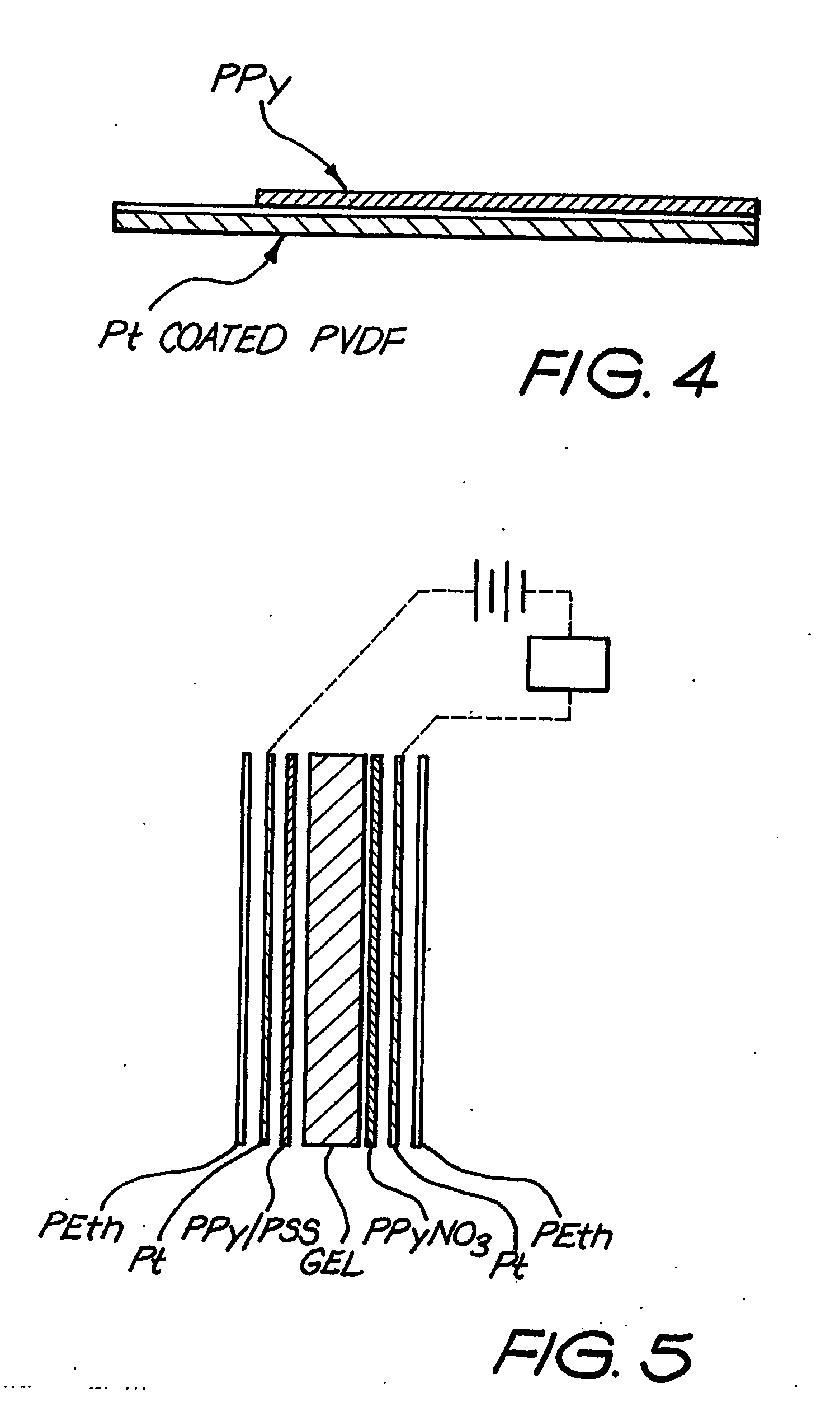
[0082] By forming the conducting polymer in the shape of a tube, it has been found that improved characteristics of the actuator may be obtained compared to the conducting polymer when provided in strip form. In particular, one or more of the electronic, mechanical and / or electrochemical properties of the actuator may be enhanced. While not being bound by theory, it is believed that a tube configuration has enhanced electrolytic efficiency compared to an actuator in the form of a strip as more of the conducting polymer comprising the tube is electrochemically accessible than a corresponding strip of the polymer.
[0228] In some preferred embodiments, the rehabilitation glove additionally facilitates movement of a patient's wrist joints.

Problems solved by technology

Additionally, for people with reduced mobility of the hand due to upper limb paralysis, such as those with cervical spinal cord injury, stroke, cerebral palsy or peripheral nerve injury, disregard for management of the maintenance of the joint range of motion of the effected hand will result in contracture and limited joint range of motion.
Such syndromes will reduce hand function, which is already limited by paralysis, and will negatively affect potential outcomes for aggressive rehabilitation techniques, such as tendon transfer surgery and functional neuromuscular stimulation.
Unfortunately, the use of such devices is not always prescribed by clinicians.
This is due, mainly, to the limitations of these devices that are in the marketplace.
These limitations include lack of secure finger placement, lack of portability, the inability to provide specialised therapy to specific joints, inflexible programming, of the device (only on or off with only one treatment modality) and, more importantly, the potential for damage to the hand to occur due to ineffective securing and placement of the fingers and thumb in the device.
The deprivation of these elements of stress after an injury has been found to be detrimental.
Indeed, profound structural and functional changes can occur which result in restricted mobility.
Nevertheless, the limitations of prior art machines applying such CPM have reduced their impact on the patient population.
Prior art weighs the hand down with a motor which, in addition to being heavy and awkward for the user (thus limiting their mobility), is non-cosmetic.
Additionally, the 15 power requirements of the motor limit the portability, especially if the device is driven from mains power.
Where the device is battery driven, the length of therapy is limited.
The cross bar configuration of the prior art allows the possibility of misalignment of the fingers in the device, thereby producing the risk of damage to the hand.
Therefore, tailoring of therapy to individual fingers and joints is not possible.

Method used


Image

  • Movement facilitation device
  • Movement facilitation device
  • Movement facilitation device

Examples


example 1

[0433] For the purpose of demonstrating characteristics of electromechanical actuators of the invention, a number of actuators were prepared and tested using polypyrrole polymer with hexafluorophosphate (PF6−) as a dopant as indicated below.

wherein n=2-4, and m=the number of repeat units of the polymer.

[0434] Specifically, the actuators were prepared:

[0435] (a) as a strip by electrodeposition onto a platinum (Pt) plate from a solution containing 0.06 M pyrrole and 0.05 M PPy / PF6 in propylene carbonate at a current density of 0.15 mA / cm2;

[0436] (b) as a tube but with no helical wire conductor using the method described above with reference to FIG. 9 and the solution and electrochemical conditions as for the preparation of the strip actuator in (a) above;

[0437] (c) as a tube with a helical wire conductor using the method described above with reference to the FIG. 9 and using the solution and electrochemical conditions as for the preparation of the strip actuator as in (a) above...

example 2

[0440] A number of tube actuators of the invention incorporating helical conductors were prepared and the performance of three samples is shown in Table 3. [0441] Resistance of the actuators were measured after locating wire inserts 104 and 105 in each end of the polymer tube, respectively. [0442] All the polymer helices were between 45 and 55 mm long. [0443] All polymer helices tested were from the same batch and prepared under a current density of 0.15 mA / cm2 for 24 hours.

[0444] A platinum (Pt) wire helix was used with a pitch of 25 turns / cm.

TABLE 3Comparison of characteristics betweenthe actuators with helical conductorPolymer HelixResistance (Ω)*Strain (%)Strain rate (% / sec)Helix 24-80.71.4Helix 34-80.81.6Helix 54-80.81.6

[0445] In all cases, the inclusion of the helical wire in the actuator resulted in improved electrochemical and actuator performance. By forming the conductor wire into a helix, the wire is able to readily extend and contract in length with expansion and redu...

example 3

[0446] The effect of the pitch of the helical wire on actuator performance was investigated. (Detail how the results were obtained.) The results set out in Table 4 suggests use of low pitch provides better performance as indicated by the increase in strain obtained. The 20 increase in strain at lower pitch is in agreement with the increase in electrochemical efficiency at lower pitch as indicated in FIG. 10.

TABLE 4Effects of pitch of helical conductor on strainunder different applied frequenciesStrain (%)Low PitchedHigh PitchedOperating Frequency(10 turns / cm)(25 turns / cm)10.0 Hz 0.100.15.0 Hz0.280.12.0 Hz0.380.21.0 Hz0.670.160.5 Hz1.00.1


PUM


Abstract

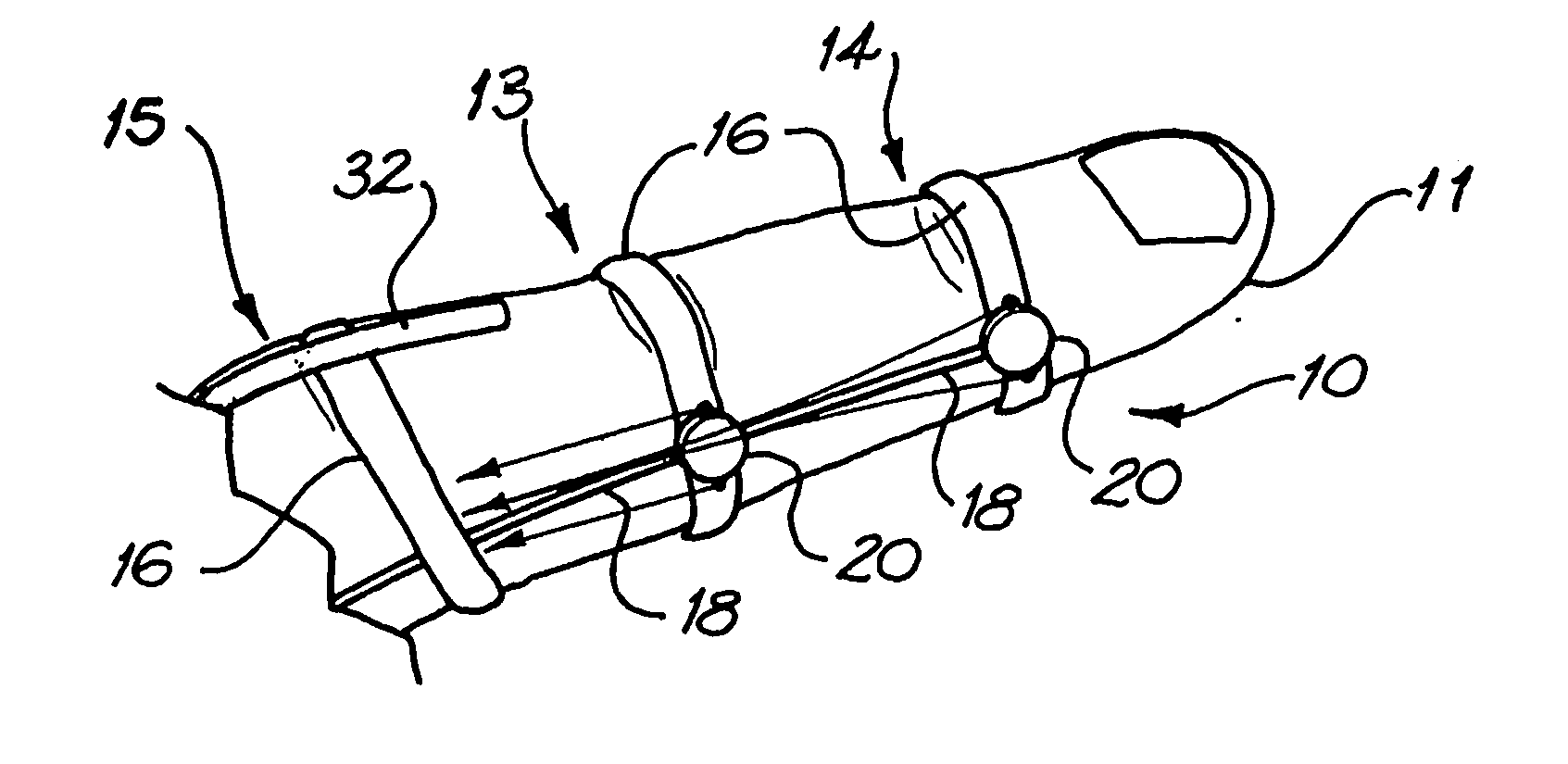
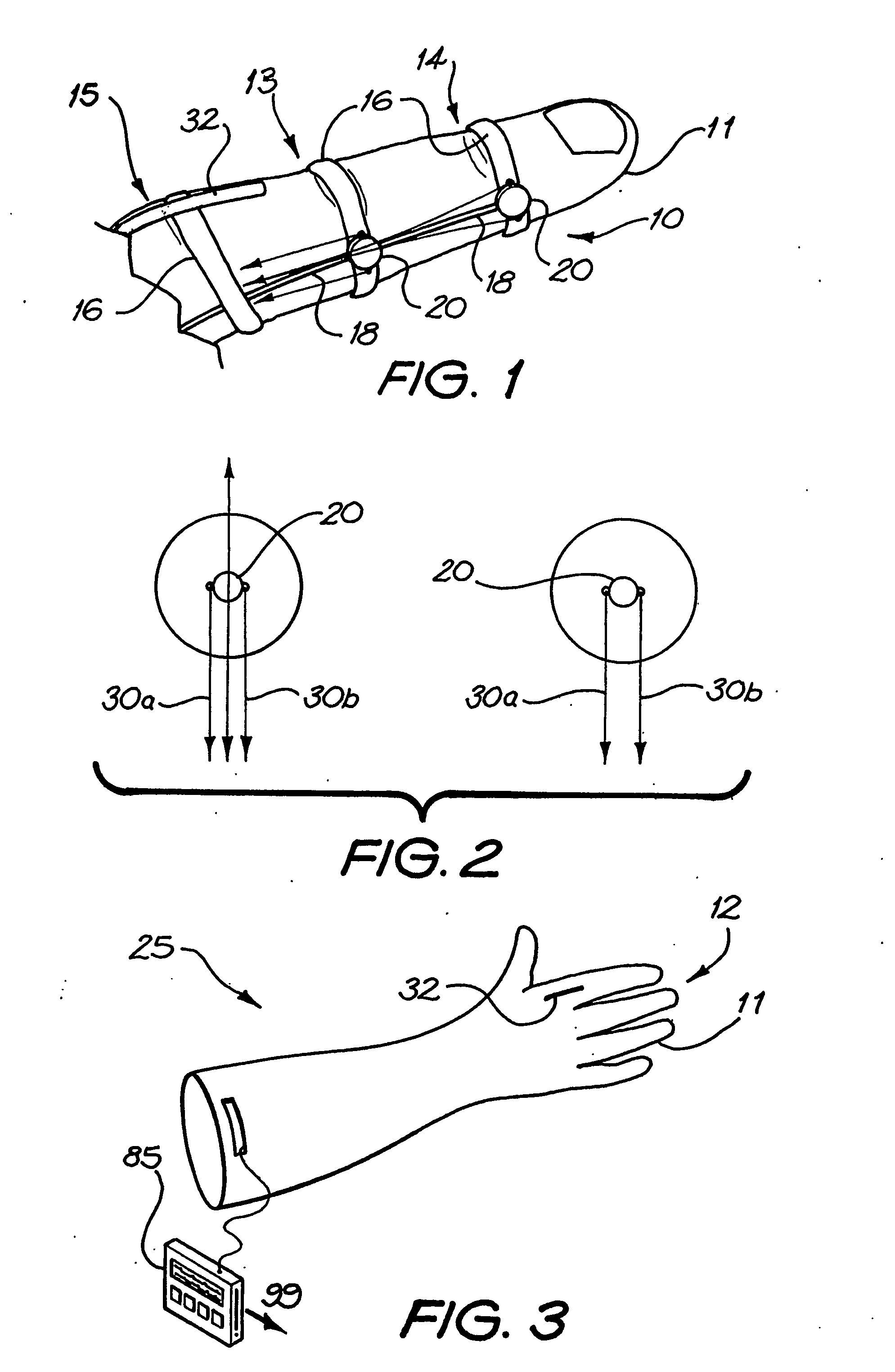
The present invention concerns movement facilitation devices for facilitating movement between a first portion of a first object and a second portion of the first object. One or more of the movement facilitation devices may be combined to form a movement device for facilitating movement of at least one joint or limb of a patient's body. One form of a movement device according to the invention is a glove which at least partially encloses the joint or limb. The invention also encompasses systems for applying Continuous Passive Motion therapy to a joint or limb of a patient using the devices of the invention. The invention also encompasses the use of shape memory materials and of conducting polymers in the devices and systems of the invention, as well as the design of force transducers and actuators that may be used in the devices.

Description

TECHNICAL FIELD [0001] The present invention relates generally to devices for facilitating movement of objects. More specifically, the present invention relates to devices for facilitating the relative movement between two portions of an object. More specifically still, the invention relates to devices for facilitating the bending or deforming of an object or a joint. In that regard, the present invention also relates to devices for moving joints in a human or non-human animal body, or mimics thereof. BACKGROUND OF THE INVENTION [0002] The loss of hand function will affect every aspect of an individuals life. This includes the ability to feed and care for themselves and the ability to work and participate in family life. For people recovering from problems such as trauma, burns or surgery affecting the hand, careful management of hand rehabilitation can influence the outcome for the patient significantly. In order to reduce the possibility of mobility difficulties occurring, includi...

Claims


Application Information

Patent Timeline
IPC IPC(8): A61H1/00A61F5/00A61F2/54A61F2/58A61F2/70A61F2/72A61F2/76A61H1/02
CPCA61F2/54A61F2/586A61F2/72A61F2002/587A61F2002/701A61F2002/704A61F2002/7625A61F2002/7635A61H1/02A61H2201/5007A63B2209/14
Inventor SCOTT, TIMOTHY RODERICK DALKEITHVARE, VERONICAAABOLFATHI, PETER PUYAWALLACE, GORDENGSPINKS, GEOFFREYMZHOU, DEZHI
Owner NORTHERN SYDNEY AREA HEALTH SERVICE
Learn More