
Film capacitor and method of manufacturing the same

a film capacitor and capacitor technology, applied in the field of film capacitors, can solve the problems of cracks formed in all samples of heat cycle tests, cracks likely to be formed in armor resin, and prior arts involve some problems, so as to reduce the risk of cracks in resin, and reduce the risk of cracks

Active Publication Date: 2006-05-18
PANASONIC CORP
View PDF5 Cites 60 Cited by
  • Summary
  • Abstract
  • Description
  • Claims
  • Application Information

AI Technical Summary

Benefits of technology

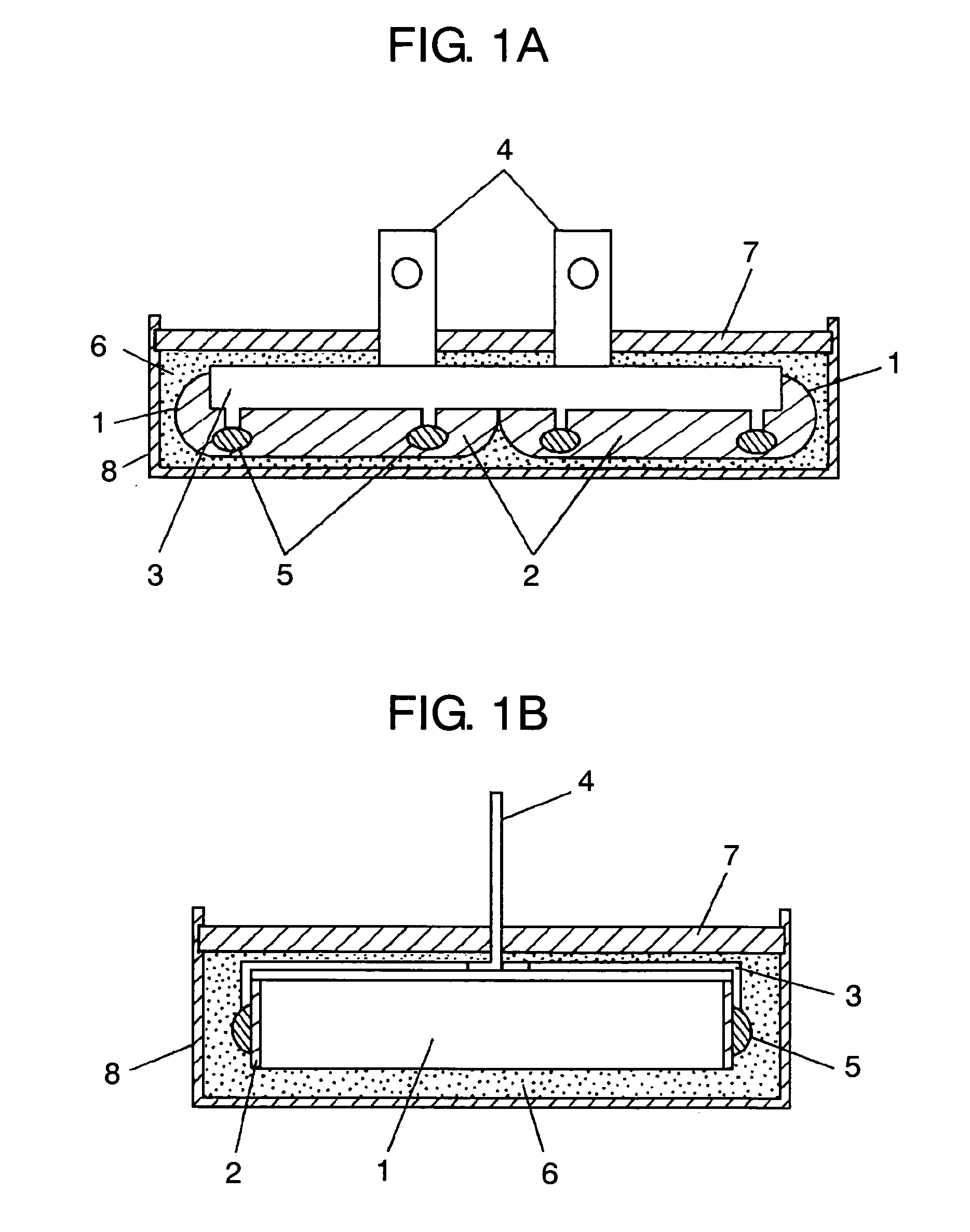
[0015] In these configurations, difference in coefficient of linear expansion may be decreased between the epoxy resin composition disposed in the uppermost layer which originates cracks, and the metal terminal. As a result, occurrence of resin cracks due to heat cycle can be prevented. Hence a film capacitor of excellent humidity resistance and high reliability is obtained.
[0017] As a result, heat diffusion can be enhanced in the epoxy resin composition disposed in the uppermost layer which originates cracks, and local thermal stress can be relaxed. As a result, occurrence of resin cracks due to heat cycle can be prevented, and a film capacitor of excellent in humidity resistance and low exothermic characteristic and high in reliability is obtained.
[0018] A manufacturing method of film capacitor of the invention comprises a step of connecting a metal terminal to electrode of film capacitor element, and a step of putting the film capacitor element into a case together with metal terminal. It further comprises a step of pouring a first epoxy resin composition, and a step of heating and curing the first epoxy resin composition for a specified time. It also comprises a step of pouring a second epoxy resin composition of smaller coefficient of linear expansion than the first epoxy resin composition, on the first epoxy resin composition. It also comprises a step of heating and curing the second epoxy resin composition for a specified time. As a result, the resin pouring time at each step is short, and the productivity can be further enhanced.

Problems solved by technology

However, the prior arts involve some problems as discussed below.
However, in the structures disclosed in document 1 and document 2, when the bus bar electrode buried in the resin is broadened, it is found that cracks are likely to be formed in the armor resin.
In particular, at ambient temperature of −40 to 100° C., cracks are formed in all samples in heat cycle test.
When the film capacitor element is covered with a soft urethane resin, the element size increases, and when expansion or shrinkage amount increases, motion of film capacitor element cannot be restrained, and repetitive stresses occur in the electrode portion of film capacitor element, thereby increasing tanδ.
Or when the film capacitor element is covered with urethane, moisture is absorbed easily, and humidity resistance is not expected.
If such resin is poured in a large amount, voids are likely to occur in the resin, and pouring time must be extended, and other problems occur in working efficiency and productivity.

Method used


Image

  • Film capacitor and method of manufacturing the same
  • Film capacitor and method of manufacturing the same
  • Film capacitor and method of manufacturing the same

Examples


embodiment 1

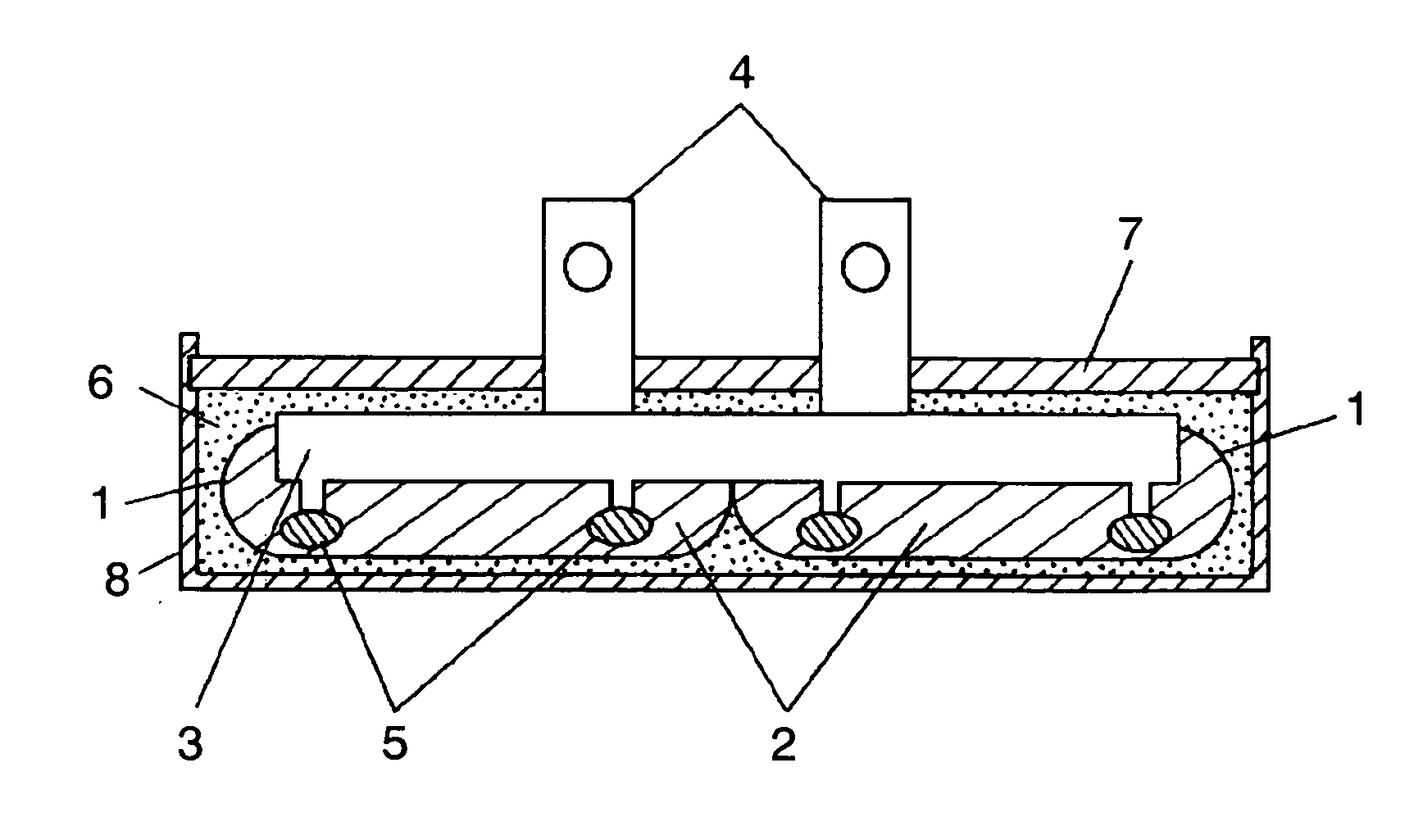
[0026] A configuration embodiment 1 of the invention is described while referring to the accompanying drawings. FIG. 1A is a side view as seen from spray electrode direction of film capacitor. FIG. 1B is a side view as seen from vertical direction of spray electrode of film capacitor.

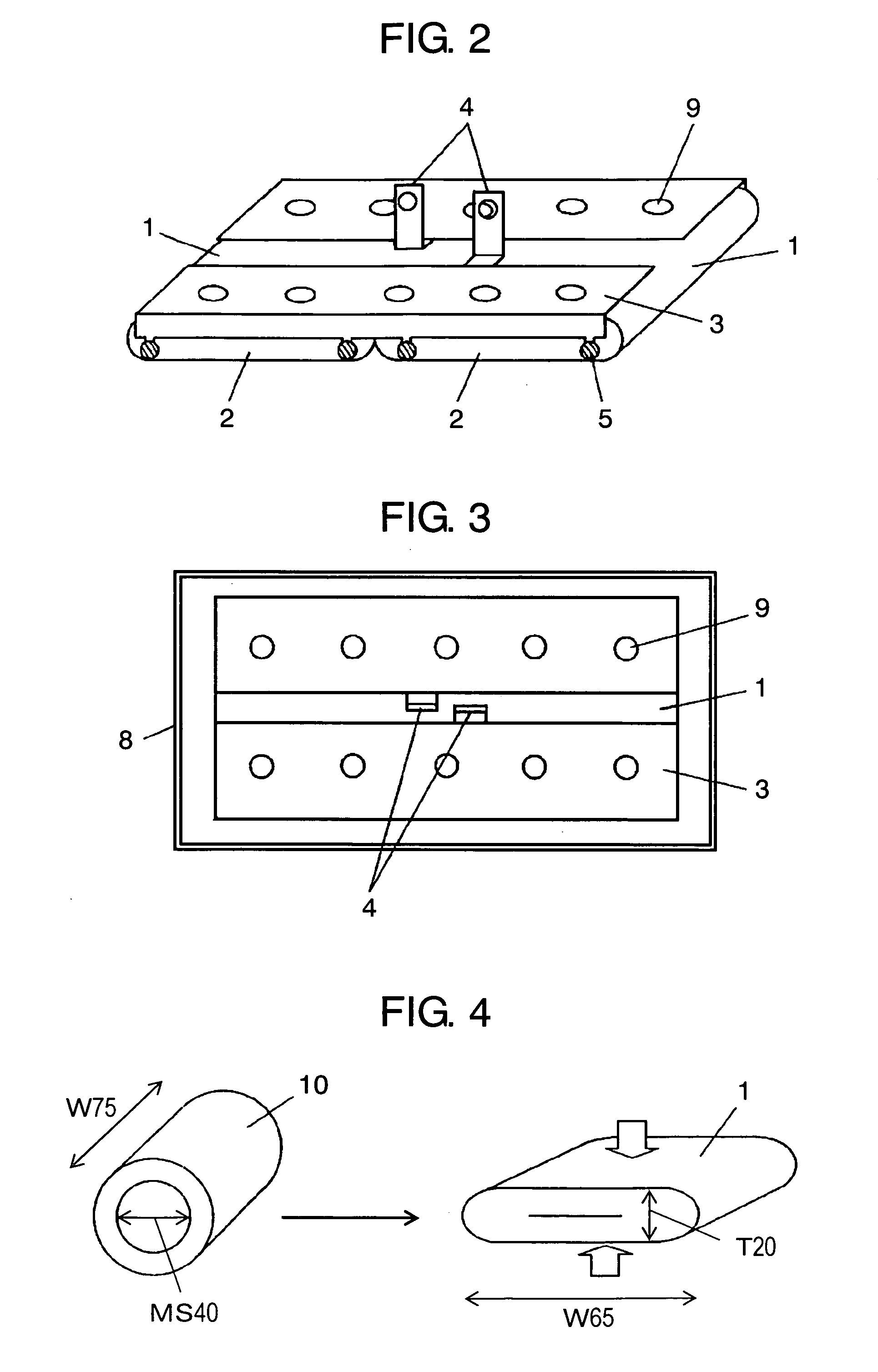
[0027]FIG. 1A and FIG. 1B show a film capacitor 100 of the invention. The film capacitor 100 has a film capacitor element 1 made of polypropylene film of thickness of about 3 μm as dielectric element. On one side of the polypropylene film, aluminum is formed as vapor deposition metal. By winding these two vapor deposition metal films, the film capacitor element 1 is formed.

[0028] Two metallized polypropylene films having metal evaporated on one side, being used in the film capacitor element 1, are provided with a fine margin not forming vapor deposition layer at one end in longitudinal direction as generally formed in metallized capacitor conventionally. Two metallized films are overlaid and wound in ...

embodiment 2

[0079] In embodiment 2, the coefficient of thermal expansion of second epoxy resin composition 7 of embodiment 1 is 22 ppm / K. All other specifications and conditions are same as in embodiment 1. As compared with embodiment 1, the coefficient of linear expansion is reduced by increasing the amount of inorganic filler to 75 wt. %.

[0080] In the film capacity of embodiment 2, test results of pouring work efficiency, appearance defects (in 100 completed products), cold heat cycle test (−40 to 105° C., 1000 cycles), and high temperature and high humidity power feed test (temperature 85° C., relative humidity 85%, direct-current voltage 600 V, 2000 hours) are shown in Table 1. Electric capacitance change rate is expressed in percentage by dividing the change amount of electric capacitance by the initial electric capacitance. Values of heat cycle test and high temperature and high humidity test are average values of five samples. Criteria of tests are same as in embodiment 1.

embodiment 3

[0081] In embodiment 3, the coefficient of thermal expansion of first epoxy resin composition 6 of embodiment 1 is 32 ppm / K. All other specifications and conditions are same as in embodiment 1. As compared with embodiment 1, the coefficient of linear expansion is raised by decreasing the amount of inorganic filler to 48 wt. %.

[0082] In the film capacity of embodiment 3, test results of pouring work efficiency, appearance defects (in 100 completed products), cold heat cycle test (−40 to 105° C., 1000 cycles), and high temperature and high humidity power feed test (temperature 85° C., relative humidity 85%, direct-current voltage 600 V, 2000 hours) are shown in Table 1. Electric capacitance change rate is expressed in percentage by dividing the change amount of electric capacitance by the initial electric capacitance. Values of heat cycle test and high temperature and high humidity test are average values of five samples. Criteria of tests are same as in embodiment 1.


PUM


Abstract

The invention provides a film capacitor and its manufacturing method suited to car-mount application, excellent in heat cycle tolerance and humidity resistance, and high in productivity, while maintaining low heat generation and low inductance characteristic. A film capacitor comprises a film capacitor element 1, a bus bar 3 as metal terminal connected to electrode 2 of this film capacitor element 1, and a case 8 for containing them, in which the film capacitor element 1 and bus bar 3 are packed within the case 8 by plural layers of epoxy resin compositions 6, 7, and the plural layers of epoxy resin compositions 6, 7 are formed in layers, and are composed so that the coefficient of linear expansion may be smallest in the epoxy resin composition 7 disposed in the uppermost layer, and therefore resin cracks can be prevented at the time of heat cycle, and a film capacitor of high reliability excellent inhumidity resistance is obtained.

Description

TECHNICAL FIELD [0001] The present invention relates to a film capacitor used in electronic appliance, electric appliance, industrial machine, and automobile, and a method of manufacturing the same. More particularly, it relates to a film capacitor used in motor driving inverter circuit of hybrid electric vihicle(HEV) or the like, for the purposes of smoothing, filter or snubber. BACKGROUND ART [0002] A metallized film capacitor is generally used by putting a capacitor element in a case to prevent invasion of surrounding humidity, and armoring by pouring various potting resins. Roles of potting resin and case are retention and insulation of contained capacitor element and components, and prevention of deterioration of characteristics. It is hence necessary to select materials excellent in mechanical strength, low water absorption, heat resistance, heat cycle resistance, and electrical characteristics (insulating performance). Potting resins include epoxy resin and urethane resin. [0...

Claims


Application Information

Patent Timeline
IPC IPC(8): H01G4/00H01G2/10H01G4/18H01G4/228
CPCH01G2/04H01G4/224Y02T10/7022H01G4/32H01G4/38Y02T10/70
Inventor SAITO, TOSHIHARUTAKEOKA, HIROKIMIURA, TOSHIHISATOMITA, MAKOTOSHIOTA, KOHEI
Owner PANASONIC CORP
Learn More