Refrigerating apparatus and fluid machine therefor

a technology of refrigerating apparatus and fluid machine, which is applied in the field of refrigerating, can solve the problems of reducing the efficiency of the operation of the compressor by the driving motor, the inability to obtain the driving force by the expansion device, and the inability to efficiently utilize waste heat, so as to achieve the effect of effectively collecting and using waste heat and reducing the dead volum

Inactive Publication Date: 2006-05-25
DENSO CORP +1
View PDF8 Cites 39 Cited by
  • Summary
  • Abstract
  • Description
  • Claims
  • Application Information

AI Technical Summary

Benefits of technology

[0018] It is, therefore, an object of the present invention to provide a refrigerating apparatus and a fluid machine to be applied to the refrigerating apparatus, in which a pump is driven by an expansion device, an influence of the pump is eliminated when the fluid machine is operated as a compressor device, and waste heat can be effectively collected and utilized even when a cooling operation by the compressor device is not required.
[0019] It is another object of the present invention to provide a fluid machine for a refrigerating apparatus, in which a dead volume is reduced when the fluid machine is operated as a compressor device.
[0020] It is a further object of the present invention to provide a refrigerating apparatus, in which waste heat is collected from a heat generating device, for example an internal combustion engine for an automotive vehicle, and a cooling operation can be continuously performed even when an operation of the heat generating device is temporarily stopped. The refrigerating apparatus can provide the cooling operation, even when a requirement for the cooling operation is temporarily and highly increased.
[0021] It is a further object of the present invention to provide a waste heat utilizing apparatus for an internal combustion engine and a method of controlling an operation of the apparatus, in which an operation of an expansion device is stopped in safe for preventing an acceleration of the expansion device when an operation for an electric power generator becomes out of control.

Problems solved by technology

In the case that the above mentioned prior art apparatus is used for the automotive vehicle, in which the waste heat from the engine is used as a heating source (instead of the burner), the driving force can not be obtained by the expansion device when an amount of the waste heat from the engine is small.
In such a case, however, the pump is also operated by the driving motor together with the compressor device, reducing efficiency of the operation for the compressor by the driving motor.
As a result, the waste heat can not be efficiently utilized for collecting the energy by the expansion device.
According to the above fluid device, however, a volume of the second fluid port inevitably becomes a dead volume for a compression operation of the fluid machine (the dead volume: a volume of the working fluid which is not pumped out and remains in a working chamber during the compression operation).
It is a problem, in particular, when an inner diameter of the second fluid port is to be designed to be larger for the purpose of allowing a large amount of the working fluid to flow into the working chamber of the expansion device, or when the amount of the working fluid pumped out from the compressor device for each rotation is designed to be smaller.
In such a refrigerating apparatus, however, a cooling operation can not be performed in the case that the waste heat can not be collected during a warming up operation of the engine.
In particular, even in the case that a large cooling capacity is required for quickly cooling down an inside of the vehicle after the vehicle has been parked under the brazing sun in summer, the cooling operation is not possible so long as the sufficient waste heat can not be collected from the engine.
According to the above proposed refrigerating apparatus, however, the cooling operation can not be performed when the engine operation is temporarily stopped, in the case that the refrigerating apparatus is applied to such a vehicle having an idle-stop operation in view of environmental protection.
It is not possible, in such a sensor-less control method, to completely prevent an operation of the generator from becoming out of a control as a result the operation steps out of its normal operational condition.
If it would happen, noise might be generated at the expansion device, and as the case may be, the expansion device might be damaged.
Furthermore, a higher voltage may be generated at the generator, causing a problem in that related electrical parts or devices may be damaged.
Even in the case that an operation of the generator is controlled by signals from position sensors, the operation of the generator may become out of control, if a controller (inverter) for the generator becomes out of order, and the rotation of the expansion device may be accelerated and damaged.

Method used


Image

  • Refrigerating apparatus and fluid machine therefor
  • Refrigerating apparatus and fluid machine therefor
  • Refrigerating apparatus and fluid machine therefor

Examples


first embodiment

[0055] A first embodiment relates to an automotive air conditioning apparatus, wherein a complex fluid machine 100 of the present invention is applied to a refrigerating cycle 30 having Rankine cycle 40.

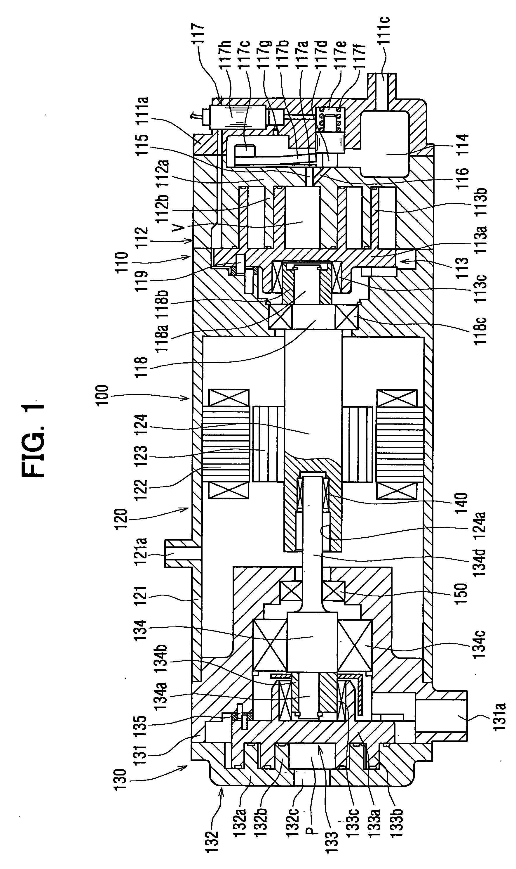
[0056] At first, a structure of the complex fluid machine is explained with reference to FIG. 1. The complex fluid machine 100 comprises an expansion-compressor device 110 having both functions of a compressor device and an expansion device, a motor generator 120 having both functions of an electric power generator and an electric motor, and a refrigerant pump 130.

[0057] The expansion-compressor device 110 has the same structure to a well-known scroll type compressor, and comprises a fixed scroll 112 provided between a front housing 111a and a motor housing 121, a movable scroll 113 facing to and rotated with respect to the fixed scroll 112, a discharge port 115 for communicating a working chamber V with a high pressure chamber 114, an inlet port 116, and a valve device 117 for ope...

second embodiment

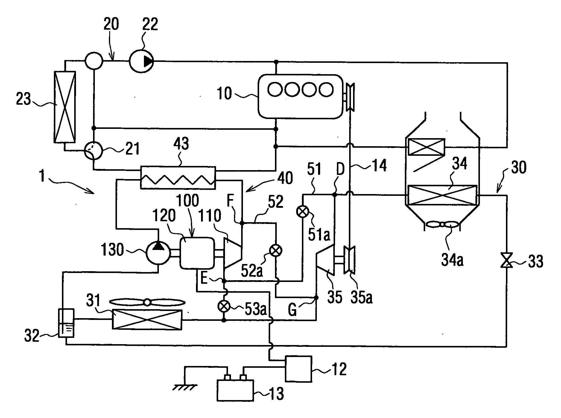
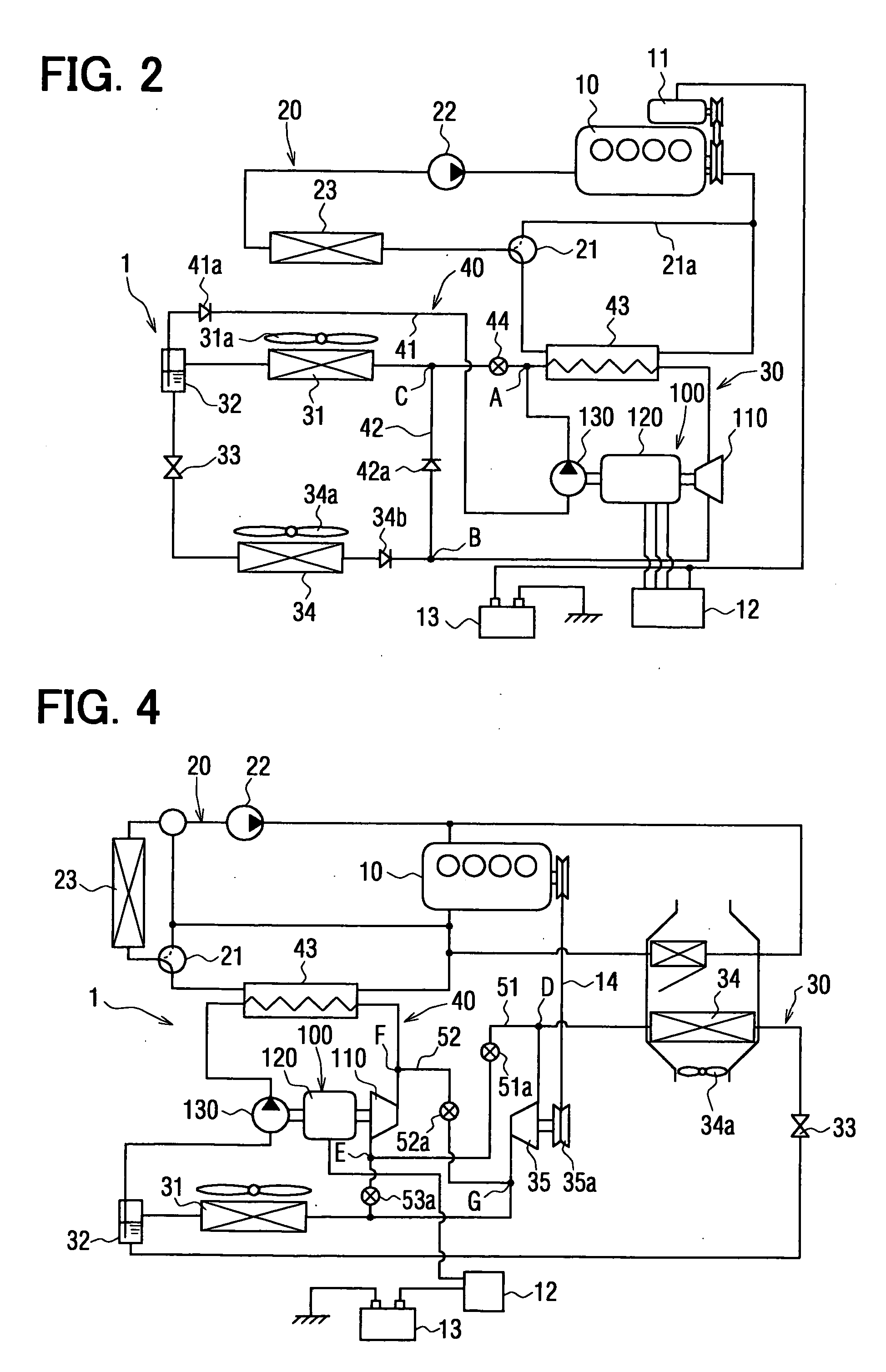
[0112] A second embodiment is shown in FIG. 4, which differs from the first embodiment in that the air conditioning apparatus 1 is applied to a vehicle (e.g. an idle-stop vehicle, a hybrid vehicle), wherein an operation of the engine 10 is temporally stopped depending on a driving condition of the vehicle (such as, an idling operation, a low speed driving, and so on). The second embodiment further differs from the first embodiment in that a main compressor device 35 is provided in the refrigerating cycle 30, and connecting passages 51, 52 and ON-OFF valves 51a, 52a, 53a are provided.

[0113] As described above, the main compressor device 35 is provided in the refrigerant cycle 30, independently from the expansion-compressor device 110. The refrigerant cycle 30 of this embodiment comprises the main compressor device 35, the condenser 31, the gas-liquid separator 32, the evaporator 34, which are connected in a circuit.

[0114] The main compressor device 35 is provided with a pulley devi...

third embodiment

Modifications of Third Embodiment

[0184] A modification of the third embodiment is shown in FIG. 14, in which the projected portion 322c is further extended in its longitudinal direction so that its forward end projects into the discharge port 115. Furthermore, an inner diameter of the discharge port 115 on a side to the high pressure chamber 114 is made smaller than that of the other portion of the discharge port. The small diameter portion 115a of the discharge port 115 is designed at an optimum value for the flow amount of the refrigerant pumped out from the expansion-compressor device 110.

[0185] According to the above modification, the volume of the discharge port 115 for the compression mode can be reduced by the projected portion 322c, namely the dead volume of the discharge port 115 can be reduced. The small diameter portion 115a substantially functions as the discharge port.

[0186] Another modification of the third embodiment is shown in FIG. 15, in which the guide portion 3...


PUM


Abstract

A complex fluid machine has an expansion-compressor device, a pump, and a motor generator, wherein the expansion-compressor device, the pump, and the motor generator are operatively connected and arranged in series, and a power transmitting device for disconnecting the pump from the motor generator, when the expansion-compressor device is driven by the motor generator so as to be operated as a compressor device.

Description

CROSS REFERENCE TO RELATED APPLICATION [0001] This application is based on Japanese Patent Application Nos. 2004-316739 filed on Oct. 29, 2004, 2004-316738 filed on Oct. 29, 2004, 2004-316740 filed on Oct. 29, 2004, 2004-336409 filed on Nov. 19, 2004, 2005-51530 filed on Feb. 25, 2005, and 2005-242879 filed on Aug. 24, 2005, the disclosures of which are incorporated herein by reference. FIELD OF THE INVENTION [0002] The present invention relates to a refrigerating apparatus having a refrigerating cycle for performing a cooling operation and Rankine cycle for collecting waste heat from a heat generating device, such as an internal combustion engine. The present invention further relates to a complex fluid machine to be applied to the refrigerating apparatus, wherein the fluid machine has a function of a compressor device for compressing and pumping out working fluid as well as an expansion device for outputting mechanical energy by expanding the working fluid operating in the Rankine...

Claims


Application Information

Patent Timeline
Patent Type & Authority Applications(United States)
IPC IPC(8): F25B27/00F25D9/00F25B1/00
CPCF01C1/0215F01C11/004F01C20/26F04C11/008F04C2240/45F25B1/04F25B27/02F25B2400/14Y02A30/274
Inventor UNO, KEIICHIASA, HIRONORITAKEUCHI, YASUHIROYOSHIDA, HIDEJIIMURA, AKIHIROINABA, ATSUSHIBAN, KOICHIYAMANAKA, TAKASHIIWANAMI, SHIGEKIKISHITA, HIROSHIOGAWA, HIROSHI
Owner DENSO CORP
Why Eureka
Try Eureka