
Optical modulator

a technology of optical modulator and extinction ratio, applied in the field of optical modulator, can solve the problems of deterioration of optical modulator characteristics, affecting the performance of optical modulators, increasing optical loss, etc., and avoiding degradation, reducing optical loss, and improving optical loss

Inactive Publication Date: 2006-05-25
SUMITOMO OSAKA CEMENT CO LTD
View PDF2 Cites 29 Cited by
  • Summary
  • Abstract
  • Description
  • Claims
  • Application Information

AI Technical Summary

Benefits of technology

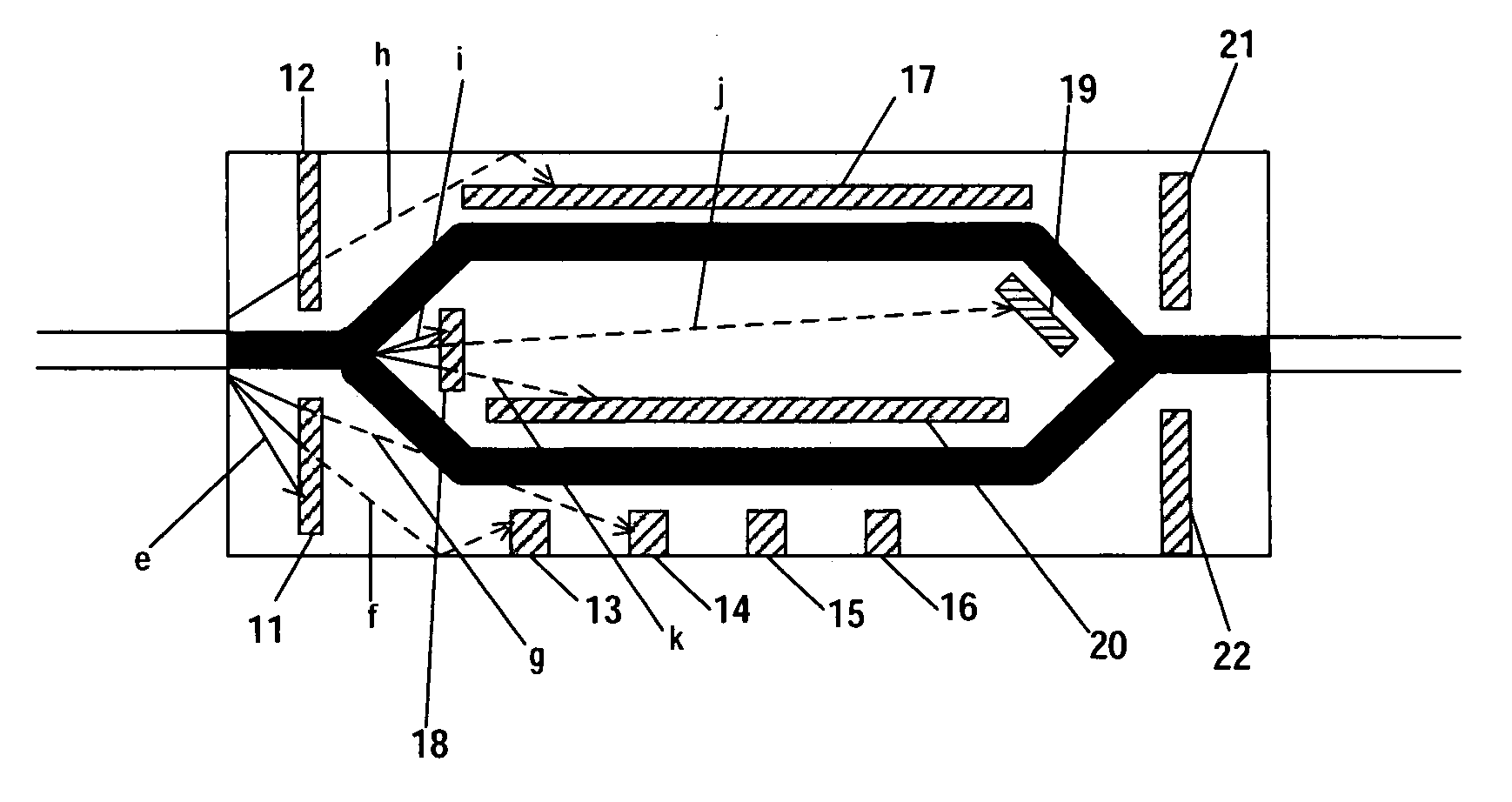
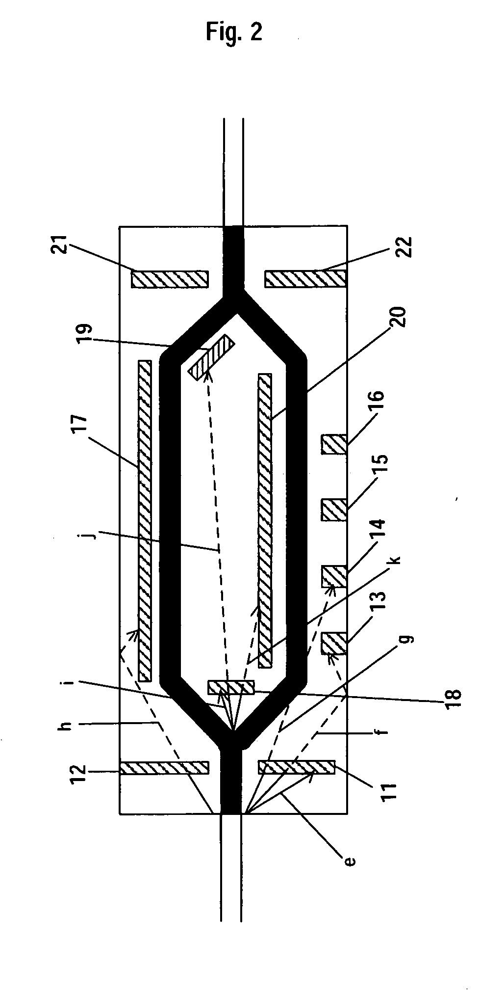
[0014] In accordance with the invention related to claim 1, the stray light rejection means avoids a diffusion of the stray light, in particular, that scatters parallel to the surface of the substrate, out of the stray light escaping from the optical waveguide formed on the substrate of the optical modulator. Thus, the stray light doesn't enter another optical waveguide in the substrate, the stray light and a signal light passing through said optical waveguide don't interfere mutually, and accordingly, no interference grating is generated. This provides the possibility of restricting a photorefractive phenomenon.
[0046] In accordance with the invention related to claim 15, in putting the light having an optical input power more than 10 mW especially, where the effect of the photorefractive phenomenon becomes significant, to the optical waveguide, it is possible to avoid the degradation of the superior extinction ratio or increase of the optical loss by rejecting the stray light and restricting mutual interference of the signal light passing through the optical waveguide and the stray light.

Problems solved by technology

Especially when the light input power is more than 10 mW, such problems become evident.
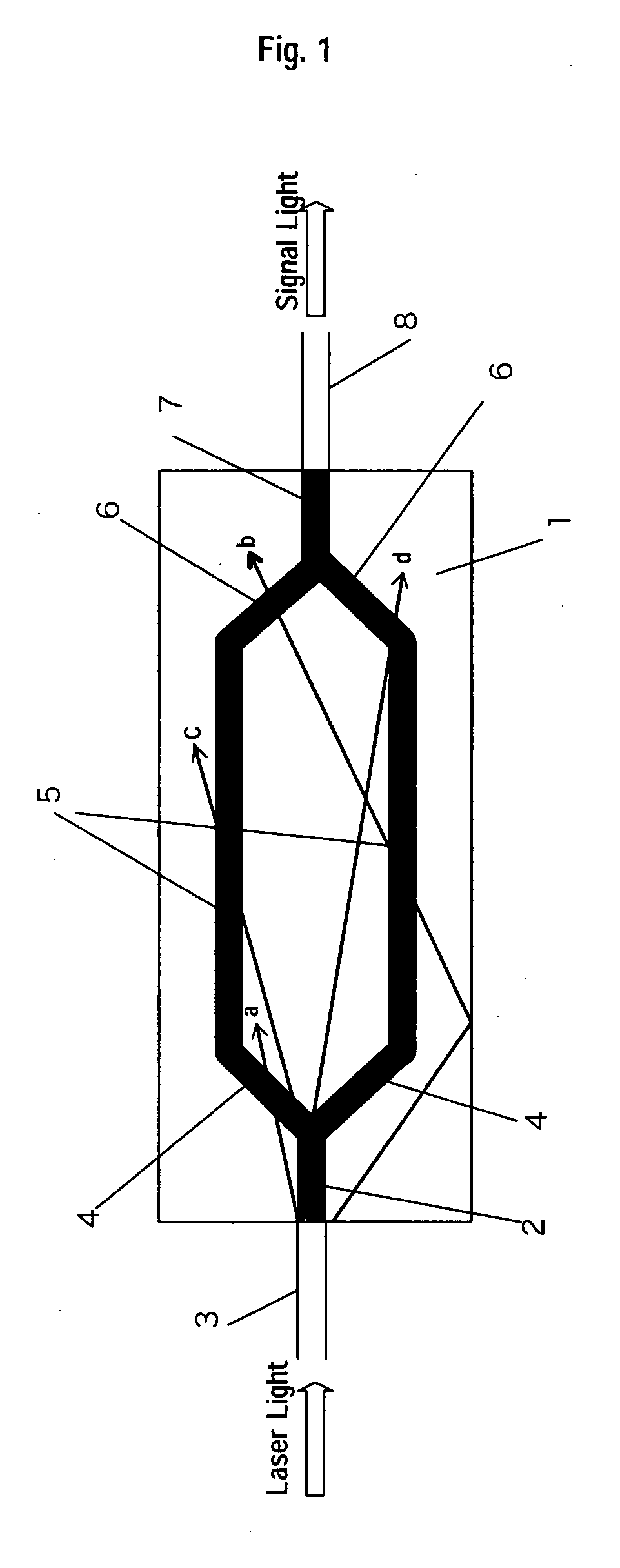
Therefore, in drive of an optical modulator for many hours, the deterioration of the optical modulator characteristics, especially degradation of the extinction ratio, increase of the optical loss, etc. becomes prominent.
This makes the length of the waveguide after the branching point of the branching optical waveguide longer, which increases the chances of interfering with the stray light and the photorefractive phenomenon tends to occur as a result.

Method used


Image

  • Optical modulator
  • Optical modulator
  • Optical modulator

Examples


second embodiment

[0081] the present invention is explained in the following.

[0082] As shown in FIG. 4, there exist stray lights 1 and m having a vector component in the thickness direction of the substrate for the stray light of the optical modulator, as well as the stray light in parallel with the surface of the substrate.

[0083] The stray light like the stray lights 1 and m that moves in the thickness direction of the substrate reflects at a base 30 or the side face of the substrate, enters the optical waveguide, and possibly interferes with the light passing through the optical waveguide.

[0084] In order to reject such stray light, as shown in FIG. 5, a low refractive index area 40 is formed such that it surrounds the optical waveguide.

[0085] By making the refractive index of the low refractive index area lower than that of the substrate, stray lights o and h that are released outside of the low refractive index area are reflected at the boundary surface of the substrate and the low refractive i...

third embodiment

[0098] Subsequently, the third embodiment is explained.

[0099] As shown in FIG. 7, a high refractive index area 42 is formed on the reverse face (base) or side face of the substrate. As the method for forming the high refractive index area, doping a material having said high refractive index into the substrate by thermal diffusion etc can form the high refractive index area.

[0100] The high refractive index area enables the stray light reflecting at the reverse face or side face of the substrate to be trapped in the high refractive index area, and therefore to be prevented from moving toward the optical waveguide again.

[0101] Further, in order to reject stray light reflection from the base or side face of the substrate of the optical modulator more effectively, antireflection treatment, for example coating these faces with an optical absorber material such as carbon black, or an antireflection coating, can be given.

[0102] Also, combining above described various embodiments if neces...


PUM

PropertyMeasurementUnit
distanceaaaaaaaaaa
frequencyaaaaaaaaaa
input poweraaaaaaaaaa

Abstract

An optical modulator restricted in a photorefractive phenomenon caused by a stray light in an optical modulator, and improved in the quenching ratio characteristics of a signal light. The optical modulator comprises a substrate consisting of a material having an electro-optic effect, an optical waveguide formed on the substrate, and a modulating electrode for allowing an electric field to work on the optical waveguide and changing the phase of light passing through the optical waveguide, characterized in that stray light removing means are provided on the surface of the substrate.

Description

BACKGROUND OF THE INVENTION [0001] (1) Field of the Invention [0002] The present invention relates to an optical modulator provided outside of a light source in order to modulate the light from the light source, in particular to an optical modulator restricting a photorefractive phenomenon in the optical modulator. [0003] (2) Related Art Statement [0004] A dense wavelength division multiplexing (DWDM) technology and high speed communication technology have been developed for optical communication systems corresponding to an increase in the demand for high speed, large capacity data communication systems recently. Particularly, although the modulation frequency of an optical modulator is mostly 10 GHz, high speed modulation more than 40 GHz would also be required from now on. [0005] As the optical modulator which corresponds to high speed modulation, the combination of CW (Continuous Wave) laser and the Mach-Zehnder(MZ) type external optical modulator (hereinafter described as LN opt...

Claims


Application Information

Patent Timeline
Patent Type & Authority Applications(United States)
IPC IPC(8): G02F1/035G02F1/03G02F1/225
CPCG02F1/0311G02F1/225G02F2201/08
Inventor ICHIKAWA, JUNICHIROICHIOKA, MASAYUKIHARA, TOKUTAKAYAMANE, YUJI
Owner SUMITOMO OSAKA CEMENT CO LTD
Learn More