Fiber used in wideband amplified spontaneous emission light source and the method of making the same

a fiber and amplified spontaneous emission technology, applied in the field of fibers and the method of making the same, can solve the problems of increasing the cost and complexity of the system, increasing the cost of the system, and increasing the cost of the system, and achieve the effect of high damage threshold power

Inactive Publication Date: 2006-05-25
NAT SUN YAT SEN UNIV
View PDF8 Cites 10 Cited by
  • Summary
  • Abstract
  • Description
  • Claims
  • Application Information

AI Technical Summary

Benefits of technology

[0026] Because it is a high temperature manufacture process, the cladding manufactured by this method is den...

Problems solved by technology

If a distributed feedback (DFB) laser is used for achieving multiple wavelengths, the cost and complexity of the system will increase.
However, the band will be insufficient because of the greatly increased communication capacity.
However, the smaller the diameter of the crystal fiber is, the greater the propagation loss will be caused.
The disadvantage of this type is that it is time consuming, needing about ten hours to diffuse the oxide layer into the crystal fiber.
The disadvantage of this type is expensive instrument.
The disadvantage of this method is that the waveguide effect is rel...

Method used


Image

  • Fiber used in wideband amplified spontaneous emission light source and the method of making the same
  • Fiber used in wideband amplified spontaneous emission light source and the method of making the same
  • Fiber used in wideband amplified spontaneous emission light source and the method of making the same

Examples


Embodiment Construction

[0036] The method of making a fiber according to the present invention mainly comprises two steps: growing step and cladding step.

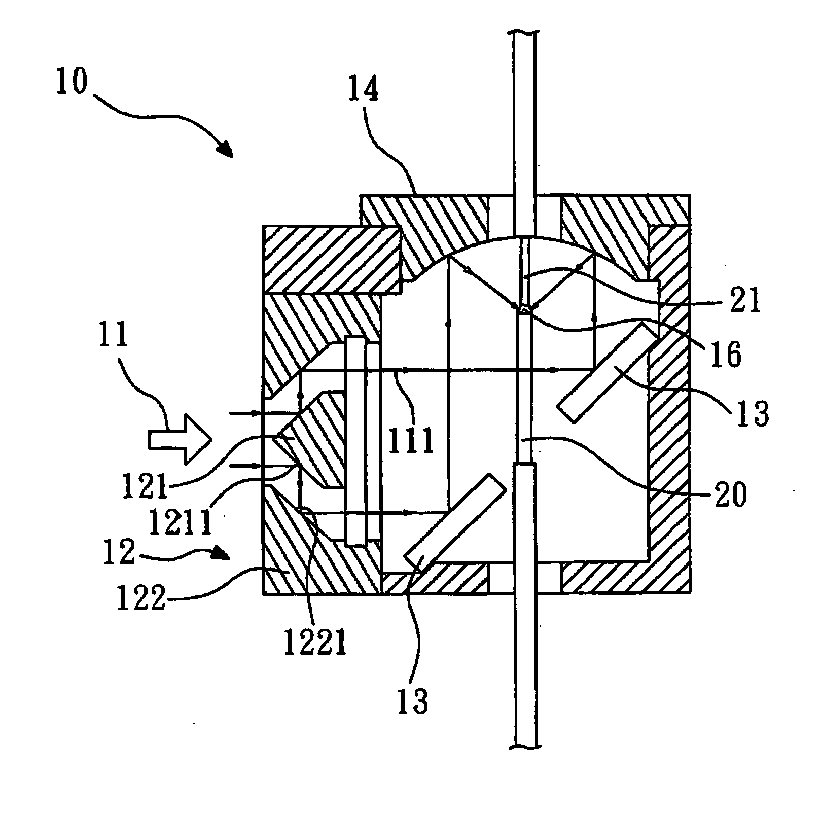
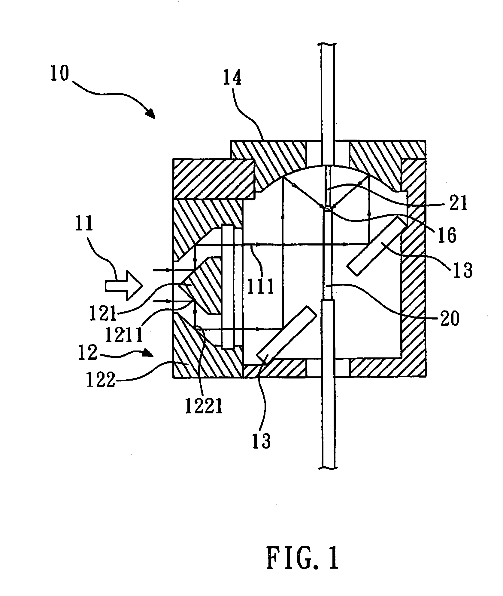
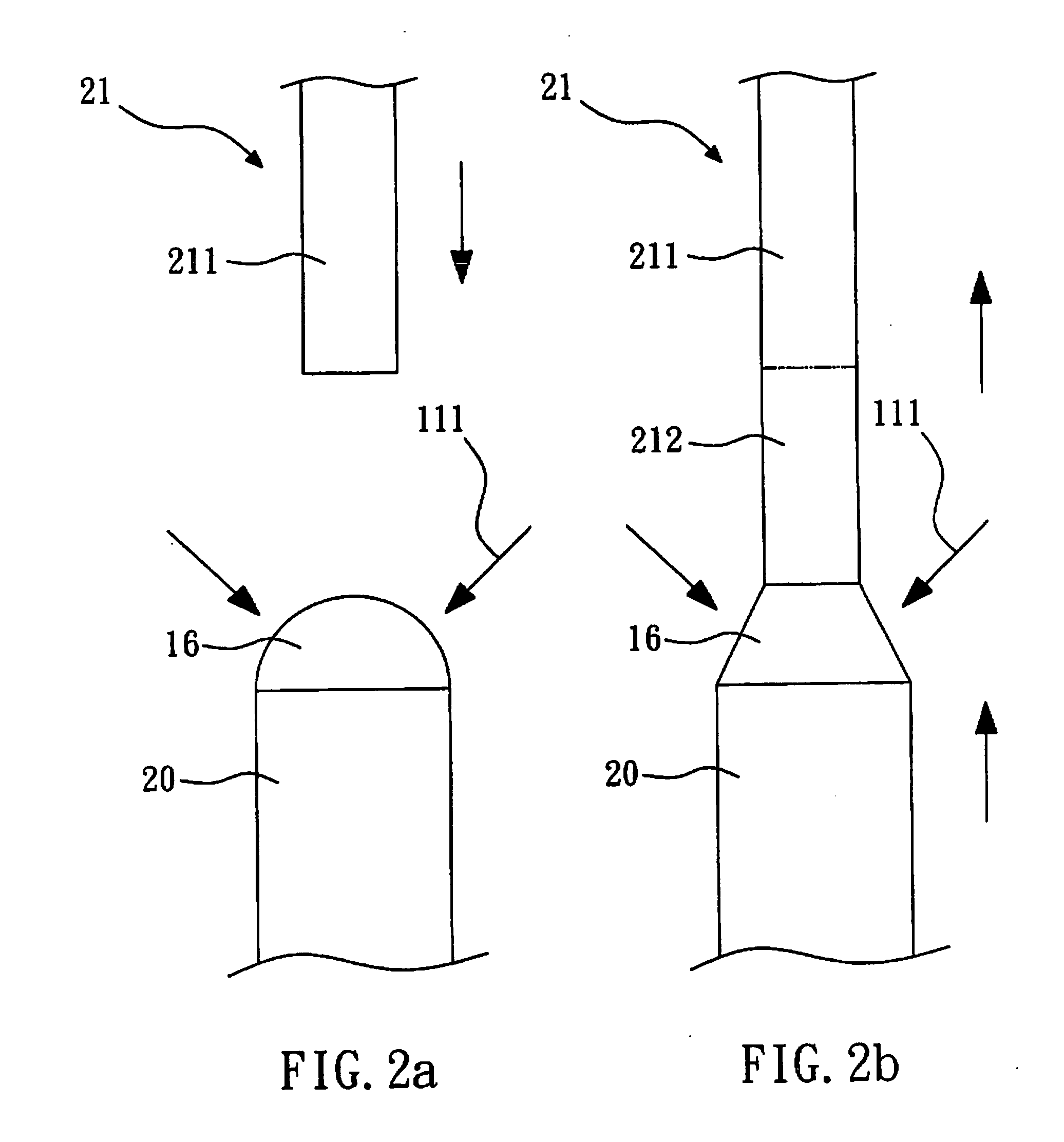
[0037]FIG. 1 shows a schematic diagram of a chamber of a fabricating apparatus for fabricating a crystal fiber according to the growing step of the present invention. The apparatus 10 is a laser heated pedestal growth (LHPG) apparatus, which is used for making a source material (for example, a source crystal rod 20) into a crystal fiber 21. In this embodiment, the material of the source crystal rod 20 is YAG crystal doped with Cr4+ ions. Alternatively, the material of the source material may be glass having garnet structure or ceramic, doped with chromium. A molten zone 16 is formed on the interface between the source crystal rod 20 and the crystal fiber 21. The apparatus 10 comprises a laser beam generator (not shown), a beam splitter 12, a bending mirror 13 and a paraboloidal mirror 14.

[0038] The laser beam generator is used for generating a CO2 laser...


PUM


Abstract

The present invention relates to a fiber having a core of crystal fiber doped with chromium and a glass cladding. The fiber has a gain bandwidth of more than 300 nm including 1.3 mm to 1.6 mm in optical communication, and can be used as light source, optical amplifier and tunable laser when being applied for optical fiber communication. The present invention also relates to a method of making the fiber. First, a chromium doped crystal fiber is grown by laser-heated pedestal growth (LHPG). Then, the crystal fiber is cladded with a glass cladding by codrawing laser-heated pedestal growth (CDLHPG). Because it is a high temperature manufacture process, the cladding manufactured by this method is denser than that by evaporation technique, and can endure relative high damage threshold power for the pumping light.

Description

BACKGROUND OF THE INVENTION [0001] 1. Field of the Invention [0002] The present invention relates to a fiber and the method of making the same, and more particularly, to a fiber having a core doped with chromium and a glass cladding, and the method of making the same. [0003] 2. Description of the Related Art [0004] Because of the breakthrough in the technology of fabricating optical fibers, it is possible to use the bandwidth of 300 nm including 1.3 μm to 1.6 μm in optical communication. The greatly increased communication capacity results in the emergence of wavelength-division multiplexing (WDM) technology, enabling tens of channels with different wavelengths transmitted simultaneously in an optical fiber. In consequence, the requirement of spectral characterization of all the optical components used in the optical transport networking systems raises. [0005] Amplified spontaneous emission (ASE) light source has low coherence due to its wideband characteristic. Such characteristic ...

Claims


Application Information

Patent Timeline
IPC IPC(8): G02B6/00
CPCH01S3/06708H01S3/06716H01S3/06795
Inventor HUANG, SHENG-LUNGLO, CHIA-YAOHUANG, KWANG-YAOTU, SHIH-YULEE, HSIAO-WENHUANG, SHENG-PANYIN, SUN-BIN
Owner NAT SUN YAT SEN UNIV
Why Eureka
Try Eureka