Implantable devices with reduced needle puncture site leakage

a technology of implantable devices and puncture sites, which is applied in the field of implantable devices, can solve the problems of significant bleeding through the resulting holes, dialysis needles may also produce undesirable bleeding at the puncture site, and the puncture hole is punctured, and achieves good biocompatibility, good handling and bending properties, and longitudinal stretch. good

Active Publication Date: 2006-06-08
WL GORE & ASSOC INC
View PDF99 Cites 73 Cited by
  • Summary
  • Abstract
  • Description
  • Claims
  • Application Information

AI Technical Summary

Benefits of technology

[0020] The combination of inner and outer porous tubes with bent fibrils and the middle layer of elastomeric material offers the highly desirable and heretofore unachieved combination of reduced leakage following removal of a needle from a puncture site, along with good biocompatibility, longitudinal stretch and good handling and bending properties. The good bending properties appear to be the result of the use of inner and outer porous tubes having bent fibrils, on either side of the elastomeric material. The bent fibrils adjacent the outer meridian of a bent tube are

Problems solved by technology

A common problem with vascular grafts is bleeding through holes punctured through the wall of a graft by suture needles or dialysis needles.
Suture needles used to create an anastomosis with these vascular grafts typically result in significant bleeding through the resulting holes that must be stopped prior to closure of the operative incision.
These dialysis needles may also produce undesirable bleeding at the puncture site upon their removal.
Suture line bleeding resulting from graft penetration by a suture needle is frequently aggravated by tension applied to the sutures during construction of the anasto

Method used


Image

  • Implantable devices with reduced needle puncture site leakage
  • Implantable devices with reduced needle puncture site leakage
  • Implantable devices with reduced needle puncture site leakage

Examples


example 2

[0078] Another example was created in the same manner as described for Example 1 except that both ePTFE tubes were tubes of greater wall thickness and had been processed by being longitudinally compressed and heat-treated to provide them with bent fibrils prior to construction of the example. These precursor tubes had a wall thickness of about 0.6 mm.

[0079] The resulting graft had a wall thickness of about 1.0 mm. It appeared that the wall thickness was the result of the relatively tight overwrap of the temporarily applied helical film wrap used during construction. When subjected to the dialysis needle cannulation test, the graft demonstrated a leakage of about 19 ml / minute. The graft showed good bending properties and offered longitudinal stretch.

example 3

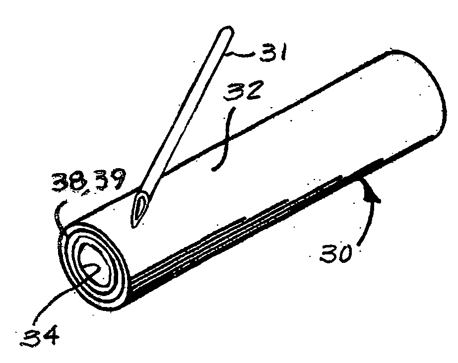
[0080] An example of a tubular graft generally according to FIGS. 3A and 3B was made using the same ePTFE tubing as used for Example 1. A length of this ePTFE tubing was fitted over a mandrel and secured as described for Example 1, and coated with the same silicone adhesive in the same manner. The second tube was, also as described for Example 1, distended to an inside diameter of 8 mm. The second ePTFE tube was then coaxially fitted over the first, adhesive-coated ePTFE tube, with tension applied to the ends of the second tube to assure that it was fully extended longitudinally (with the fibrils of the microstructure in a substantially straight condition). A temporary helical wrap of a strip of thin ePTFE film was uniformly applied about the outer surface of the outer tube. The coaxial tubes were then longitudinally compressed together, by applying a compressive force to both tubes by pushing the opposing ends of the tubes toward each other by hand. No wrinkling or gross deformatio...

example 4

[0085] An example was made similarly to Example 1, except that the outer ePTFE tube was replaced with a thinner ePTFE film tube made by helically wrapping two layers of a strip of ePTFE film (about 2.5 cm width, 50 micron fibril length, 0.01 mm thickness and 0.3 g / cc density) about the surface of a 10 mm diameter mandrel. The film was applied in a “bias-ply” fashion by helically wrapping first in one direction, then returning, back over the first wrap. The pitch of the helical wrap resulted in adjacent edges of the helical wrap being about 2.5 mm apart as measured in the direction of the tube length. The film-wrapped mandrel was heated for 10 minutes in an air convention oven set at 370° C., removed from the oven and allowed to cool. After cooling, the helically-wrapped film tube was removed from the mandrel.

[0086] The film tube was carefully fitted over the outer surface of the adhesive-coated, tensioned silicone tube. Tension was applied to the ends of the film tube, causing it t...


PUM

PropertyMeasurementUnit
Timeaaaaaaaaaa
Timeaaaaaaaaaa
Radiusaaaaaaaaaa

Abstract

A prosthetic implantable device that offers a reduction in fluid loss when the device is punctured, such as by a dialysis needle or suture needle, and the needle is subsequently removed. The device may be made to be thin and flexible, and with longitudinal stretch, in order that it also offers good handling and kink resistance to a surgeon. While the device is preferably of tubular form, flat sheets or other forms may also be made. The device includes inner and outer layers of a porous material having a microstructure of nodes interconnected by bent fibrils, and having void spaces between adjacent bent fibrils. The inner and outer layers are joined by an elastomeric adhesive that may interpenetrate the void spaces of the adjacent surfaces of the inner and outer layers, that is, the inner surface of the outer layer and the outer surface of the inner layer. Optionally, a middle layer of an elastomeric material may also be provided, joined to the inner and outer porous layers by the interpenetrating elastomeric adhesive. The device is preferably a vascular graft and more preferably a vascular graft for kidney dialysis.

Description

FIELD OF THE INVENTION [0001] The present invention relates to the field of implantable devices such as vascular grafts, patches and the like. BACKGROUND OF THE INVENTION [0002] A common problem with vascular grafts is bleeding through holes punctured through the wall of a graft by suture needles or dialysis needles. Commercially available vascular grafts are most conventionally made of polyethylene terephthalate fabric or porous polytetrafluoroethylene tubing but materials of biologic origin such as human or bovine arteries or veins have also been used. Suture needles used to create an anastomosis with these vascular grafts typically result in significant bleeding through the resulting holes that must be stopped prior to closure of the operative incision. Dialysis treatment of individuals suffering from renal failure requires that the blood of the individual be withdrawn, cycled through a dialysis machine and returned to the individual. A common approach to providing the necessary ...

Claims


Application Information

Patent Timeline
IPC IPC(8): B32B37/00B29C65/00A61M37/00A61F2/06A61F2/04A61F2/02
CPCA61F2/06A61L27/16F16L11/04A61L27/34A61L27/507A61L27/56B29C35/02B29C41/08B29C63/18B29C66/344B29D23/001B29K2021/00B29K2027/18B29K2105/246B29L2009/00B29L2023/007B32B1/08B32B3/26B32B5/142B32B25/08B32B25/20B32B27/00B32B27/08B32B27/16B32B27/18B32B27/304B32B27/322B32B27/40B32B2250/03B32B2250/24B32B2250/40B32B2264/105B32B2307/546B32B2307/722B32B2307/762B32B2535/00B32B2597/00C08L27/18
Inventor HOUSE, WAYNE D.CULLY, EDWARD H.POND, DANIEL B.
Owner WL GORE & ASSOC INC
Why Eureka
Try Eureka