Low thermal conductivity thermal barrier coating system and method therefor

a thermal barrier and low thermal conductivity technology, applied in the field of coating systems, can solve the problems of increasing the need to correspondingly increase the durability of high temperature components within the engine, and the thermal conductivity of tbc materials such as ysz, so as to improve the tbc technology and reduce the cost. , the effect of low thermal conductivity

Inactive Publication Date: 2006-06-08
GENERAL ELECTRIC CO
View PDF42 Cites 8 Cited by
  • Summary
  • Abstract
  • Description
  • Claims
  • Application Information

AI Technical Summary

Benefits of technology

[0008] In view of the above, it can be appreciated that further improvements in TBC technology are desirable, particularly as TBCs are employed to thermally insulate components intended for more demanding engine designs. A TBC having multiple beneficial effects, such as a low thermal conductivity, strong resistance to erosion and impact, sufficiently long life and phase stability would allow for higher component surface temperatures and reduced coating thickness for the same surface temperature. Reduced TBC thickness, especially in applications like combustors often employing relatively thick TBCs, would result in a significant cost reduction and weight benefit.

Problems solved by technology

However, as operating temperatures increase, the high temperature durability of the components within the engine must correspondingly increase.
TBCs formed by these methods have a lower thermal conductivity than a dense ceramic of the same composition as a result of the presence of microstructural features or defects and pores in the TBC microstructure.
However, the thermal conductivities of TBC materials, such as YSZ, are known to increase over time when subjected to the operating environment of a gas turbine engine.
Multiple layers are thus often added to some YSZ TBCs to correct deficiencies resulting in unwanted increased thickness of the coating system.
However, the above solutions may be undesirable for reasons relating to cost, weight, component life and engine efficiency.
As illustrated above, a thermal barrier coating, such as YSZ, while being known for providing certain environmental protection benefits to a coating system may not provide other important properties needed for an adequate coating.
Often, prior thermal barrier coatings provide specific protection or benefits in one particular area, but fail to provide benefits in other important areas required by thermal barrier coating systems.

Method used


Image

  • Low thermal conductivity thermal barrier coating system and method therefor
  • Low thermal conductivity thermal barrier coating system and method therefor
  • Low thermal conductivity thermal barrier coating system and method therefor

Examples


Embodiment Construction

[0024] Embodiments of the invention are generally applicable to components subjected to high temperatures and particularly to components, such as the high and low pressure turbine nozzles and blades, shrouds, combustor liners and augmentor hardware of gas turbine engines. While the advantages are particularly suitable for high pressure turbine blades and the other afore-mentioned components, the teachings described herein are generally applicable to any component on which a thermal barrier coating may be used to protect the component from a high temperature environment.

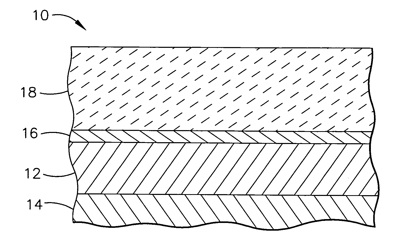
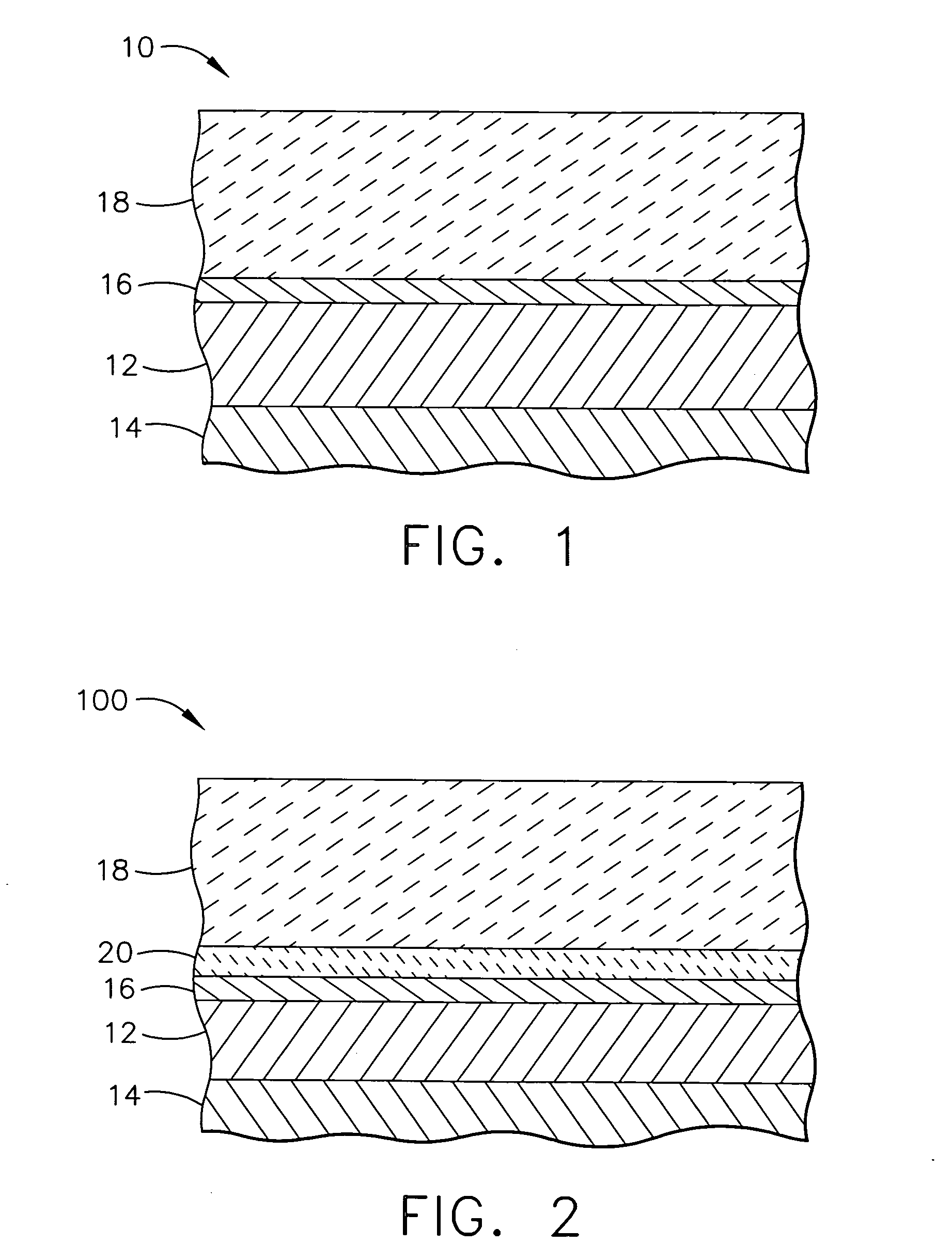
[0025] Referring to FIG. 1, a TBC system 10 of a first embodiment is shown. The TBC system 10 includes a metallic bond coat 12 that overlies the surface of a substrate 14, the latter of which is typically a superalloy and the base material of a component, such as a turbine blade. The bond coat 12 may be any suitable bond coat(s) including, but not limited to diffusion coatings, such as a diffusion aluminide or diffus...


PUM

PropertyMeasurementUnit
thicknessaaaaaaaaaa
thicknessaaaaaaaaaa
thicknessaaaaaaaaaa

Abstract

In accordance with an embodiment of the invention, a thermal barrier coating for inclusion in a thermal barrier coating system is provided. The thermal barrier coating comprises a compound having a rhombohedral phase. In accordance with another embodiment of the invention, a thermal barrier coating is provided that comprises a compound having the formula of: A4B3O12, wherein A is at least one rare earth element; and B is selected from the group consisting of Zr, Hf and mixtures thereof.

Description

CROSS-REFERENCE TO RELATED APPLICATION [0001] The subject application shares certain attributes with U.S. Ser. No. ______, entitled, “Sintering Resistant, Low Conductivity, High Stability Thermal Barrier Coating / Environmental Barrier Coating System For A Ceramic-Matrix Composite (CMC) Article To Improve High Temperature Capability” and with U.S. Ser. No. ______, entitled, “Thermal Barrier Coating / Environmental Barrier Coating System For A Ceramic-Matrix Composite (CMC) Article To Improve High Temperature Capability”, each of which are filed concurrently herewith.GOVERNMENT RIGHTS [0002] The invention was made in part under contract number N00421-00-3-0443 awarded by the Government (Navy). Accordingly, the Government has certain rights in this invention.FIELD OF THE INVENTION [0003] This invention relates to coating systems suitable for protecting components exposed to high temperature environments, such as the hot gas flow path through a gas turbine engine. More particularly, the in...

Claims


Application Information

Patent Timeline
Patent Type & Authority Applications(United States)
IPC IPC(8): B32B15/04B32B9/00
CPCC04B35/486C04B41/009C04B41/5042C04B41/87C04B2111/0025C04B2235/3224C04B2235/3225C04B2235/3227C04B2235/3229C04B2235/76C04B2235/767C23C4/105C23C30/00F01D5/288C04B41/4527C04B35/565C04B35/806F05D2230/90F05D2300/611C23C28/325C23C28/321C23C28/3215C23C28/345C23C28/3455C23C4/11
Inventor BOUTWELL, BRETT ALLEN ROHRERDAROLIA, RAMGOPALJOHNSON, CURTIS ALANSPITSBERG, IRENEGORMAN, MARK DANIELGAO, YAN
Owner GENERAL ELECTRIC CO
Why Eureka
Try Eureka