Integrated hydroponic and wetland wastewater treatment systems and associated methods

a wastewater treatment system and integrated technology, applied in biological water/sewage treatment, water cleaning, multi-stage water/sewage treatment, etc., can solve the problems of large scale, large footprint, and frequent failure of systems, and achieve less land intensive, less land intensive, and reduced undesirable characteristics of influents

Active Publication Date: 2006-06-15
DHARMA IP
View PDF64 Cites 33 Cited by
  • Summary
  • Abstract
  • Description
  • Claims
  • Application Information

AI Technical Summary

Benefits of technology

[0011] The present invention provides a wastewater treatment system and method that are less land intensive than previous systems, as well as combining the advantages of a plurality of remediation techniques. The present invention has a smaller footprint than previously disclosed wetlands, reduces undesirable characteristics of an influent, and has a low yield, i.e., low proportion of matter needing disposal.
[0013] The wastewater treatment systems and methods of the present invention are amenable to the treatment of, for example, but not intended to be limited to, domestic wastewater, industrial waste or process water, urban runoff, agricultural wastewater or runoff, and even biological sludges. The systems are capable of handling a flow range of approximately 2000-2,000,000 gal / day. The types of contaminants that can be treated in the system include suspended particles, nutrients, metals, simple organics (oxygen-demanding substances), and synthetic or complex organics. The undesirable characteristics typically desired to be remediated include, but are not intended to be limited to, average biological oxygen demand (BOD), average total suspended solids (TSS), total nitrogen, and concentration of oil and grease. The systems of the present invention can reduce BOD to <10 mg / L, TSS to <10 mg / L, and total nitrogen to <10 mg / L.
[0028] Hydraulic design integrates passive forward flow, tidal flow, and recycle flow into one system. The process design in various embodiments integrates wetland and lagoon treatment technology. The process design of the present invention also includes elements of environmental and ecological engineering design that significantly improve the state of the art of wastewater treatment in general, and wetland wastewater treatment in particular.

Problems solved by technology

A negative aspect of such systems is that they are very land-intensive, requiring roughly on the order of 100 times as much land area as a conventional treatment plant, or, in terms of capacity, as much as 30-40 acres per 106 gallons of wastewater treated per day unless other treatment processes are incorporated into the constructed wetlands.
These systems have been shown to frequently fail, however.
Failure is manifested as the upstream gravel tends to become clogged with biosolids, permitting the influent to bypass the clogged region and pass substantially untreated to a downstream region.
Ultimately the gravel becomes so clogged that design wastewater treatment is substantially compromised.
Although this root zone treatment method can provide advanced secondary treatment effluent, its application is limited by climate and available sunlight to approximately 5% of the United States.
The large treatment footprint of water hyacinth treatment systems prohibits enclosure in greenhouses for almost all economically viable applications.
Among the problems encountered with root zone / activated sludge technology is that the clarifiers employed do not scale well when the size of the system is reduced beyond a certain point.
In addition, operator qualifications are high for activated sludge systems, adding to the expense of running the system.
Root zone / activated sludge technology has been known to digest in situ a large fraction of the biosolids produced and maintained within the treatment system, thereby reducing system biosolids yield.
Lack of recycled biosolids substantially degrades the treatment performance of the activated sludge treatment element.

Method used


Image

  • Integrated hydroponic and wetland wastewater treatment systems and associated methods
  • Integrated hydroponic and wetland wastewater treatment systems and associated methods
  • Integrated hydroponic and wetland wastewater treatment systems and associated methods

Examples


first embodiment

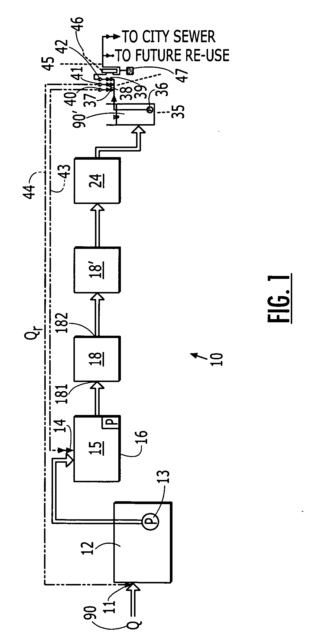
[0041] A schematic of the present invention (FIG. 1) illustrates the flows through this system 10, beginning with wastewater influent 90 entering via an inlet 11 into a covered anaerobic reactor 12, which serves to perform an initial organic and solids removal. In this vessel 12 the solids from the influent 90 settle, and anaerobic bacteria feed on the solids and wastes in the liquid.

[0042] Following treatment in the anaerobic reactor 12 for a predetermined period, for example, in a particular embodiment 1.5 days comprises an exemplary retention time, the wastewater 90 is channeled via a pump 13 to the inlet 14 of an attached growth pretreatment filter 15. This filter 15 is at least intermittently exposed to atmospheric oxygen. The filter 15 achieves removal of organics and solids and denitrification.

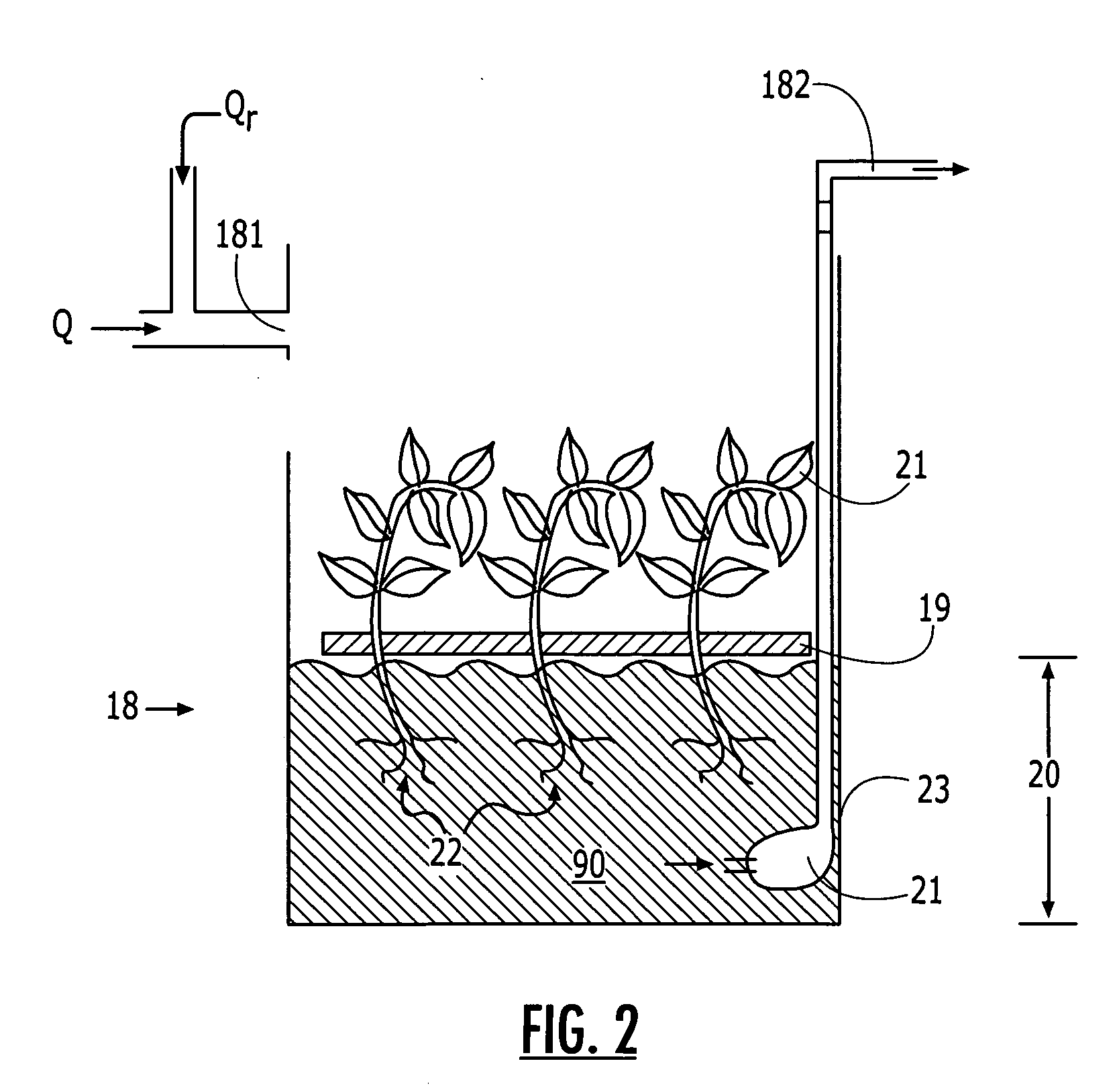
[0043] Fluid is collected from the bottom 16 of the filter 15 and is pumped 17 to an inlet 181 of a first hydroponic reactor 18 (FIG. 2). Herein the term hydroponic reactor is taken to...

second embodiment

[0056] In the invention, the system 50 (FIG. 4) comprises a pretreatment module 51, into which influent 90 is channeled and permitted to reside for a predetermined period. The wastewater 90 is then channeled to via a pump 52 to the inlet 14 of an attached growth pretreatment filter 15 as above. This filter 15 is at least intermittently exposed to atmospheric oxygen. The filter 15 achieves removal of organics and solids and denitrification.

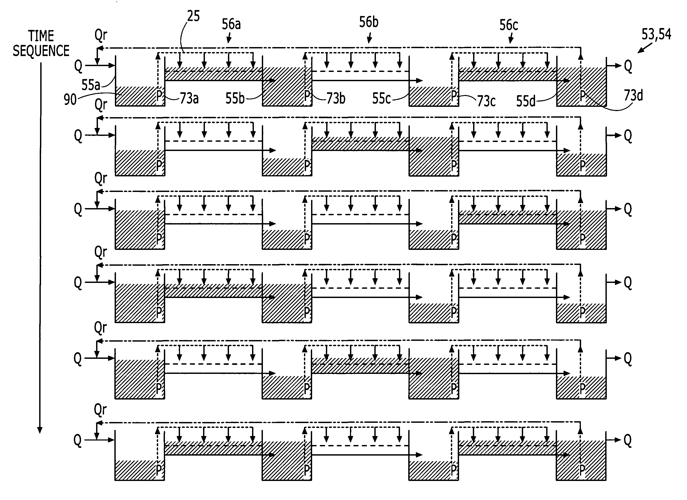
[0057] Water from the filter 15 is transferred to a pair 53,54 of tidal vertical-flow wetlands (TVFW), each of which comprises alternating series of lagoons 55 and VF wetland cells 56. Each lagoon 55 (FIG. 2) is comparable to the hydroponic reactor 18 discussed above. Each lagoon 55 is adapted to maintain a population of grazing aquatic invertebrates, such as, for example, filter-feeding zooplankton.

[0058] Each wetland cell 56 comprises a module 24 as illustrated in FIG. 3. The wetland cell 56 has a depth 67 that is less than that 58 of the lagoon...


PUM

PropertyMeasurementUnit
particle sizeaaaaaaaaaa
heightaaaaaaaaaa
porosityaaaaaaaaaa

Abstract

The wastewater treatment systems have a plurality of treatment modules between the inlet and the outlet, each for treating water with a selected process. Influent is directed to a covered anaerobic reactor, and then to an attached growth pretreatment filter that is at least intermittently exposed to atmospheric oxygen. Following the filter is a hydroponic reactor followed by a vertical-flow wetland. A second embodiment includes, following the filter, a tidal vertical-flow wetland and a pump for recycling water exiting the wetland upstream of the filter.

Description

CROSS-REFERENCE TO RELATED APPLICATIONS [0001] This application claims priority to application Ser. No. 10 / 294,496, “Integrated Hydroponic and Fixed-Film Wastewater Treatment Systems and Associated Methods,” filed Nov. 14, 2002, now U.S. Pat. No. 6,830,688, which itself claimed priority to provisional application 60 / 333,203, filed on Nov. 14, 2001, entitled “Integrated Hydroponic and Fixed-Film Wastewater Treatment Systems and Associated Methods”, and 60 / 389,637, filed on Jun. 18, 2002, entitled “Residential Wastewater Treatment System and Associated Method”. The disclosures of these applications are incorporated hereinto by reference.BACKGROUND OF THE INVENTION [0002] 1. Field of the Invention [0003] The present invention relates to wastewater treatment systems and methods, and, more particularly, to such systems and methods for wastewater treatment that are nonchemically based. [0004] 2. Description of Related Art [0005] Wastewater treatment via “natural” means, i.e., without the ...

Claims


Application Information

Patent Timeline
Patent Type & Authority Applications(United States)
IPC IPC(8): C02F3/32C02F1/00C02F1/32C02F3/04C02F3/06C02F3/28C02F3/30C02F9/00
CPCC02F1/32C02F3/04C02F3/06C02F3/286C02F3/302C02F3/308C02F3/32C02F3/327C02F9/00C02F2103/001C02F2301/043C02F2303/02Y02W10/37Y02W10/10
Inventor AUSTIN, DAVID C.MACIOLEK, DAVID J.VON ROHR, J. ROB
Owner DHARMA IP
Why Eureka
Try Eureka