Deposition of samples and sample matrix for enhancing the sensitivity of matrix assisted laser desorption/ionization mass spectrometry

a matrix assisted laser and mass spectrometry technology, applied in the direction of instruments, particle separator tube details, separation processes, etc., can solve the problems of limited detection sensitivity, large inhomogeneous sample spots, and limited broader applications of maldi mass spectrometry, so as to reduce the amount of analyte, improve the signal-to-noise ratio, and not waste analyte

Active Publication Date: 2006-06-29
WISCONSIN ALUMNI RES FOUND
View PDF20 Cites 26 Cited by
  • Summary
  • Abstract
  • Description
  • Claims
  • Application Information

AI Technical Summary

Benefits of technology

[0008] The MALDI targets in accordance with the invention having very small sample spots disposed thereon have several advantages over other MALDI targets presently available. The small sample spots result in better signal-to-noise ratios, req

Problems solved by technology

Unfortunately, broader applications for MALDI mass spectrometry have been limited by the fact that detection sensitivity is restricted by sample handling and preparation techniques.
Many of these limitations stem from the fact that current techniques for preparing sample spots on MALDI targets produce relatively large inhomogeneous sample spots.
These large spots require a considerable amount of sample and often waste sample because only a small fraction of the sample spot is actually irradiated for ion generation during MALDI mass spectrometry.
Although quill pens have been used to

Method used


Image

  • Deposition of samples and sample matrix for enhancing the sensitivity of matrix assisted laser desorption/ionization mass spectrometry
  • Deposition of samples and sample matrix for enhancing the sensitivity of matrix assisted laser desorption/ionization mass spectrometry
  • Deposition of samples and sample matrix for enhancing the sensitivity of matrix assisted laser desorption/ionization mass spectrometry

Examples


example 1

Spot Size Analysis

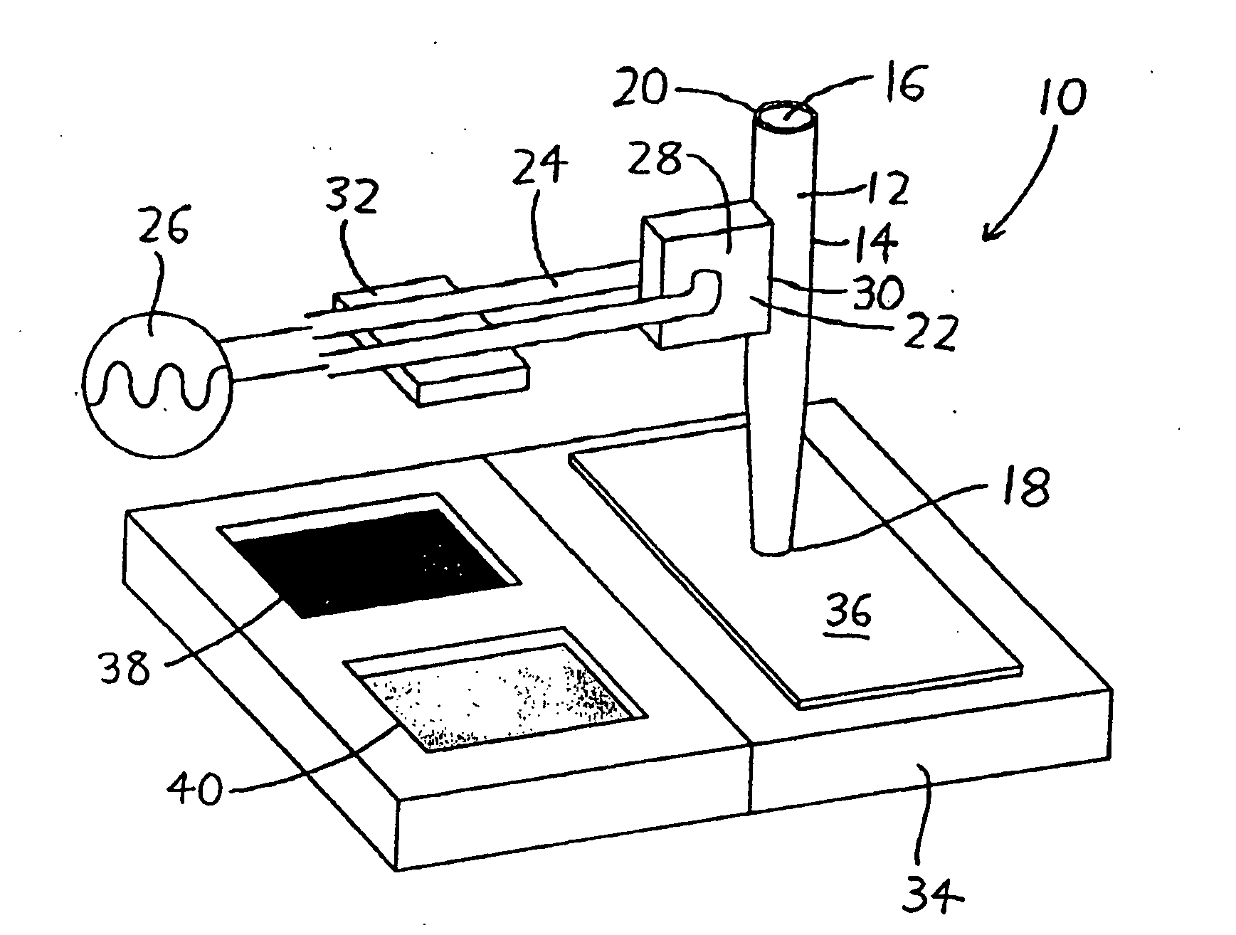
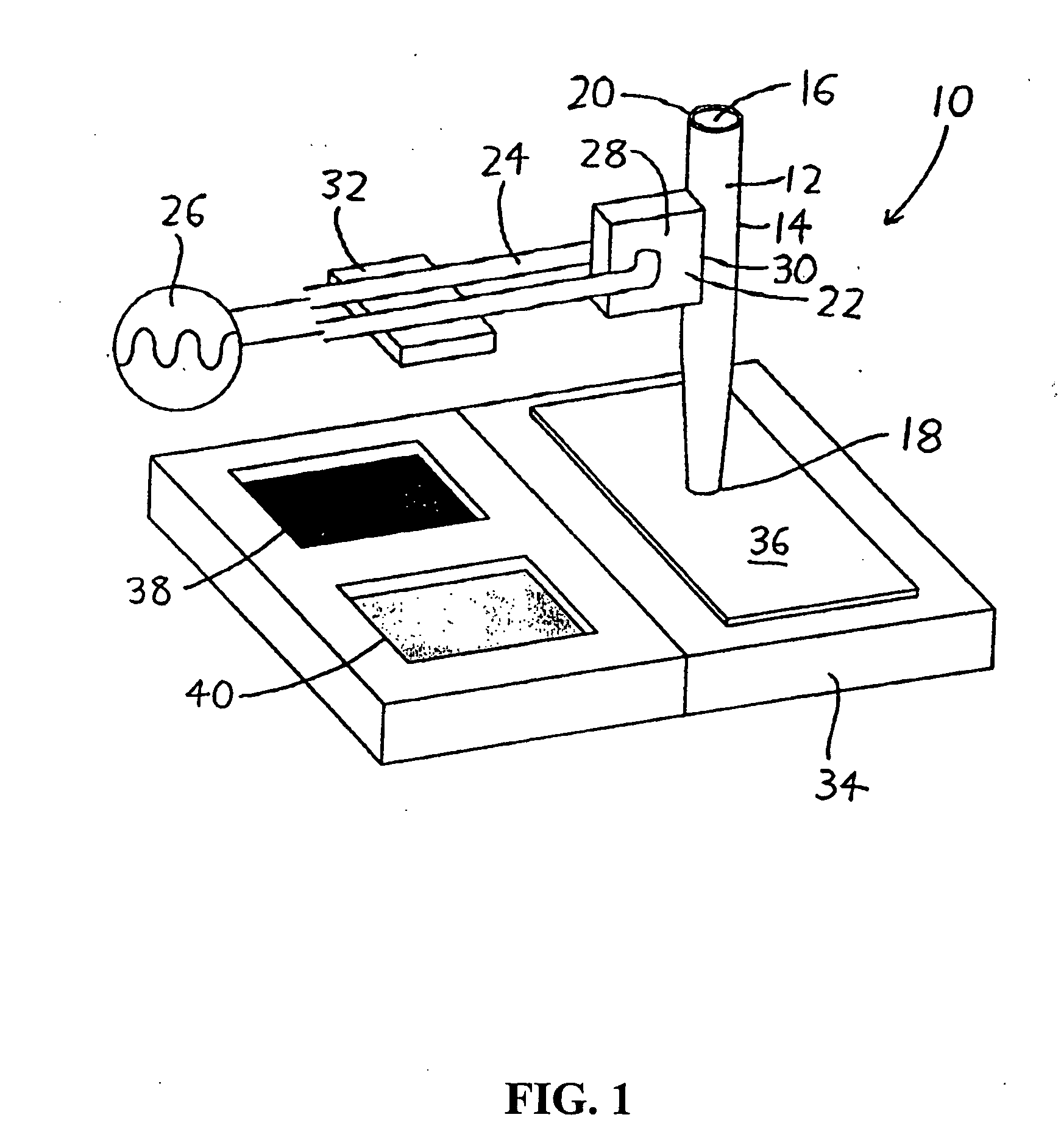
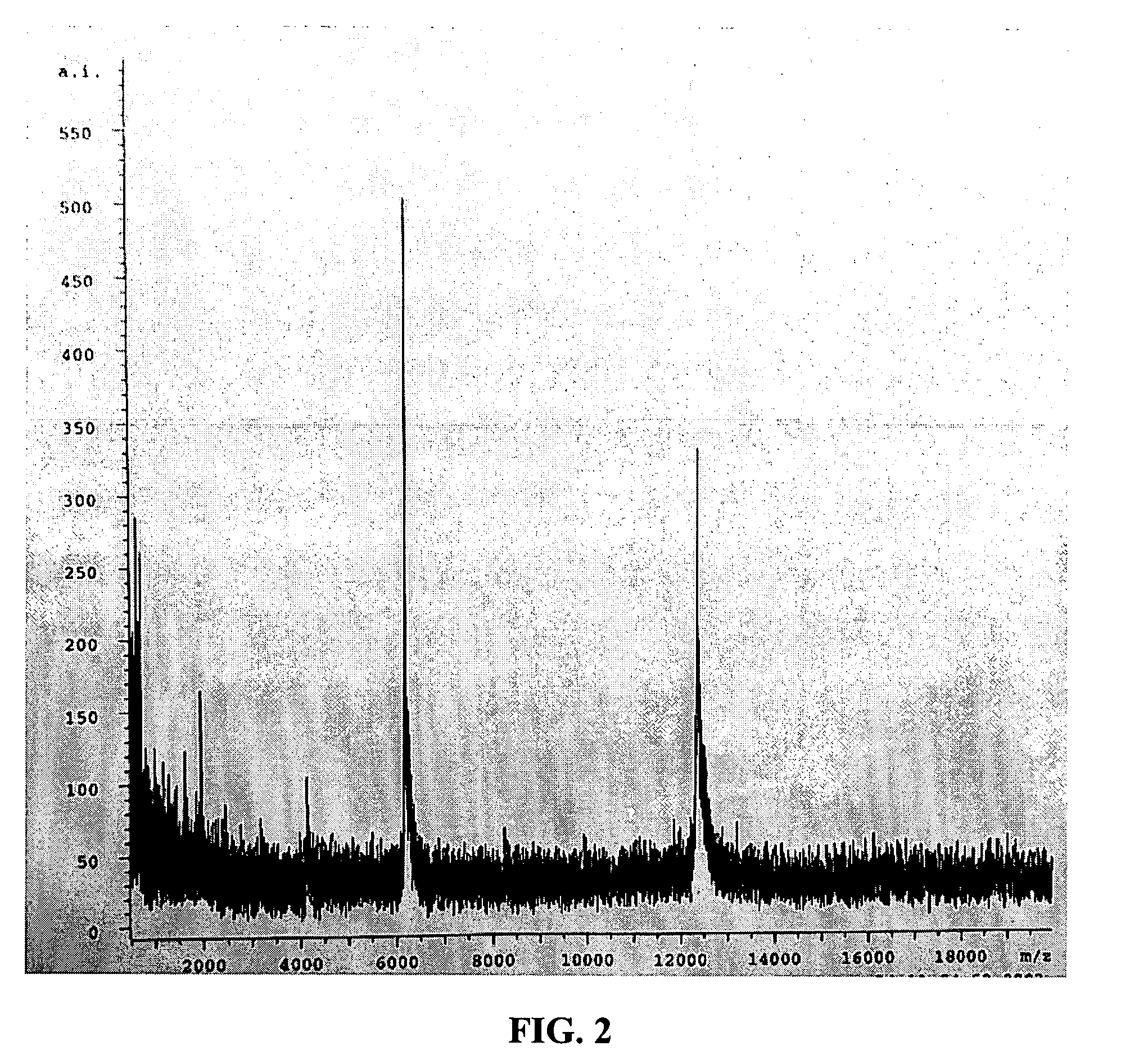
[0038] This Example demonstrates the effect of spot size on signal-to-noise ratio. A 10-mM solution of cytochrome C, with deionized (DI) water as solvent, was deposited on a stainless-steel MALDI target using the ultrasonically actuated microplotter described in U.S. Patent Application Publication No. 2004 / 0071601, then covered with a solution of α-CHCA matrix material dissolved in 30% DI water / 70-% methanol solution. First, the dispenser was loaded with the cytochrome C solution and driven at 660 kHz and 1 V for a period of time sufficient to deposit approximately 75-μm-wide spots of the protein in a grid across the MALDI target. The dispenser was then cleaned with DI water and loaded with matrix solution. Two separate sets of matrix spots were deposited overlaying different portions of the spotted protein grid. One set of matrix spots was deposited at 660 kHz and 4 V to produce approximately 70-μm-wide spots, while the other set was deposited at 660 kHz and 2 V ...

example 2

Deposition Pattern Analysis

[0039] A comparison between four different means of protein and matrix deposition was performed, using the same protein solution and matrix material described in Example 1. In addition to the previously described spots of matrix deposited on spots of protein, spots of matrix were deposited on a continuous coating of protein, a continuous coating of matrix was deposited on spots of protein, and a continuous coating of matrix was deposited on a continuous coating of protein. The continuous coatings were deposited by using the ultrasonically actuated microplotter to draw lines spaced so closely that an essentially uniform sheet of matrix or protein resulted. The lines were deposited at a speed of 1000 μm / s, a frequency of 660 kHz, and an amplitude of 1 V (for the protein) or 3V (for the matrix). Analysis was performed in the same mass spectrometer, with the same settings, used in Example 1. Mass spectra were obtained, as before, by targeting the laser onto t...


PUM

PropertyMeasurementUnit
Diameteraaaaaaaaaa
Diameteraaaaaaaaaa

Abstract

The present invention relates to small sample spots for MALDI targets and methods for producing the same. The sample spots are composed of a layer of matrix material and a layer of analyte. In some instances, the samples spots have diameters of no more than 50 micrometers or even smaller. The sample spots are deposited onto a MALDI target substrate using ultrasonic deposition from a nozzle.

Description

BACKGROUND [0001] Matrix-assisted laser desorption / ionization (MALDI) mass spectrometry has proven to be a useful analytical tool in the fields of proteomics and genomics. In these fields, MALDI has been used for protein identification and characterization, peptide fingerprinting, and DNA sequencing. Samples that are commonly analyzed using MALDI include peptides, proteins, polymers, oligonucleotides, oligosaccharides, tissue samples, and drugs. [0002] Unfortunately, broader applications for MALDI mass spectrometry have been limited by the fact that detection sensitivity is restricted by sample handling and preparation techniques. Many of these limitations stem from the fact that current techniques for preparing sample spots on MALDI targets produce relatively large inhomogeneous sample spots. These large spots require a considerable amount of sample and often waste sample because only a small fraction of the sample spot is actually irradiated for ion generation during MALDI mass sp...

Claims


Application Information

Patent Timeline
IPC IPC(8): H01J49/04
CPCG01N2001/282G01N2035/1034H01J49/0418
Inventor BARNES, DAVID M.LARSON, BRADLEY J.LAGALLY, MAX G.VESTLING, MARTHA M.
Owner WISCONSIN ALUMNI RES FOUND
Why Eureka
Try Eureka