

Magnetic resonance imaging of prostate cancer
a technology of magnetic resonance imaging and prostate cancer, applied in the field of magnetic resonance imaging of prostate cancer, can solve the problems of often lacking definition and clarity of images produced
- Summary
- Abstract
- Description
- Claims
- Application Information
AI Technical Summary
Benefits of technology
Problems solved by technology
Method used
Image

Examples
example 1
Cell Cultures and Evaluation of the Extent of PSMA Expression in Prostate Cell Lines
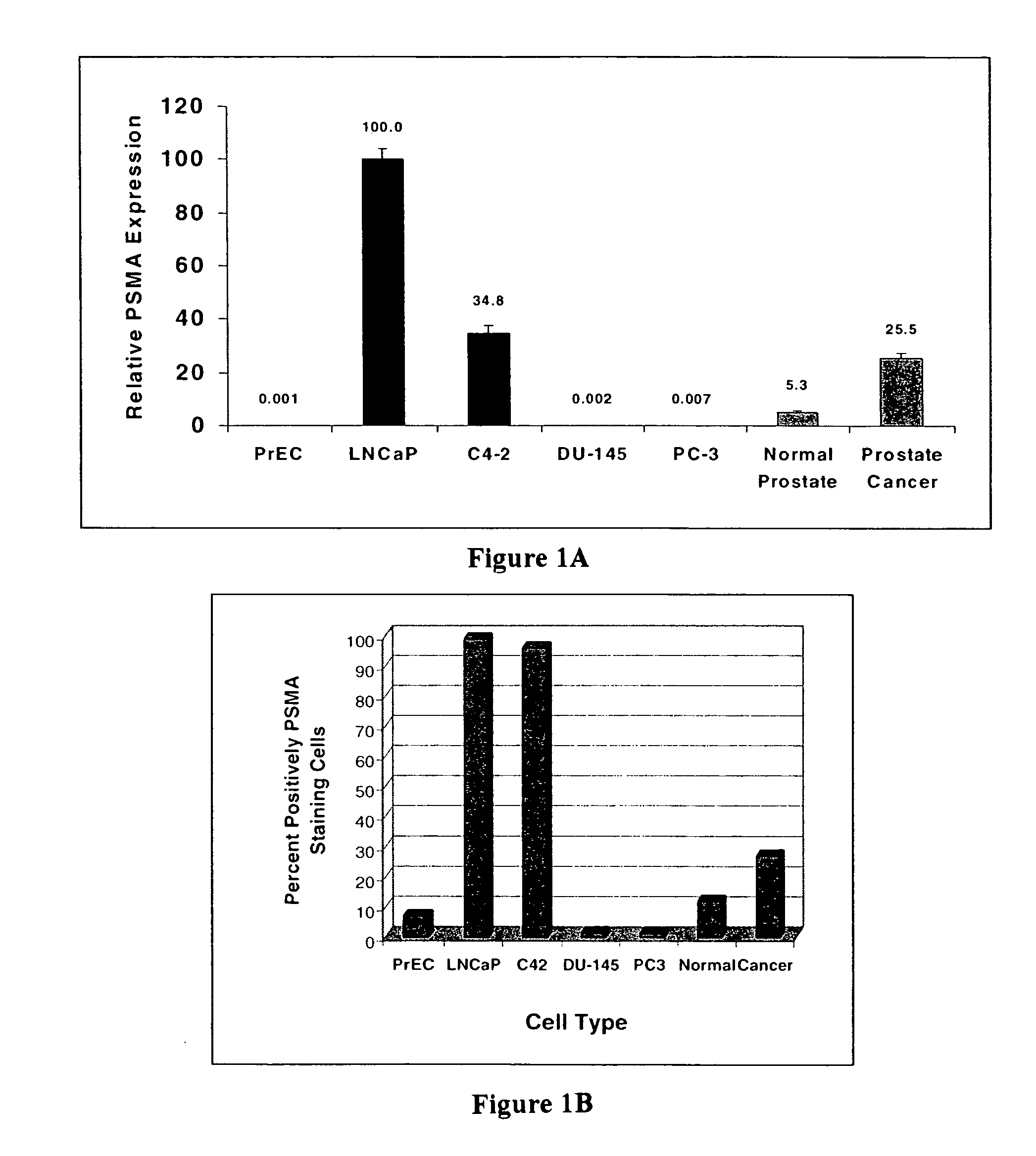
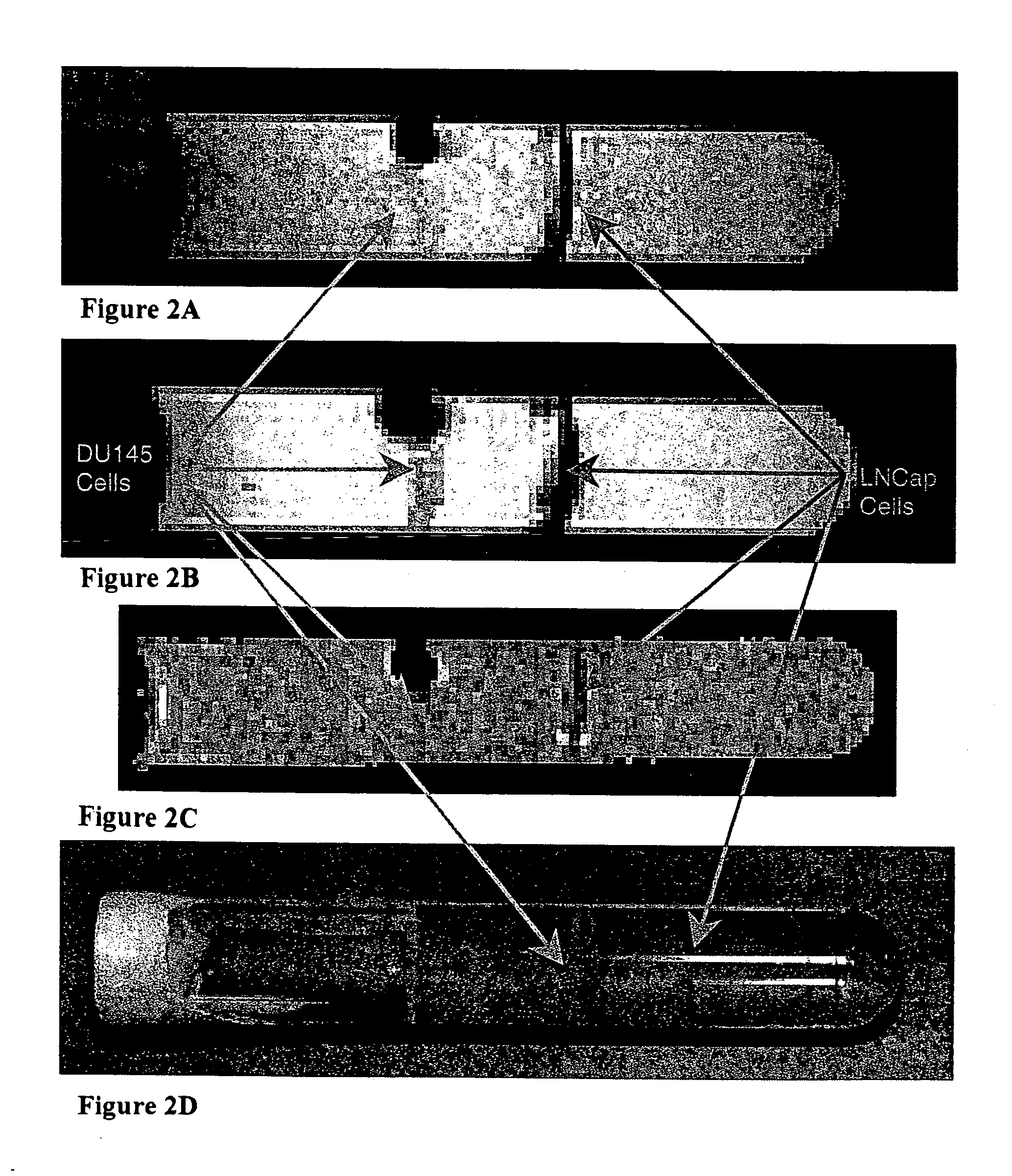
[0062] In order to determine the extent of PSMA expression in human tissue and cultured prostate cell lines, polymerase chain reaction and flow cytometry were performed. The expression of PSMA was examined by RT-PCR and flow cytometry in human tissues and in several cultured human prostate cancer cell lines. The findings indicate that it is highly-expressed in LNCaP and C4-2 cells, but almost absent in DU-145 and PC-3 cells. Monoclonal antibody MAb 3C6 conjugated to SPIONs selectively bound to LNCaP cells was readily detected as a significant change in signal intensity in magnetic resonance images obtained by standard methods. The same 3C6-conjugated SPIONs showed weak binding to DU-145 cells, giving rise to only small signal perturbations in the MR images.
Materials
[0063] Fluorescein-conjugated streptavidin was obtained from Molecular Probes (Eugene, Oreg.). Anti-PSMA antibody (clone 3C6) was pur...
example 2
Detection of Bound SPION-Conjugated 3C6 Antibodies Using MRI
[0070] Using the cell lines described above, the ability to bind and detect PSMA on the cells using superparamagnetic nanoparticle-ligand conjugates was evaluated.
Antibody Conjugation to Superparamagnetic Beads and Cell Labeling
[0071] DYNABEADS MyOne Streptavidin was obtained from Dynal Biotech (Oslo, Norway), and MACS Streptavidin Microbeads were obtained from Miltenyi Biotec (Bergisch Gladbach, Germany). DYNABEADS MyOne Streptavidin superparamagnetic beads (1.05+ / −0.10 μm diameter, 37% iron oxide w / w, polystyrene coating) and MACS Streptavidin MicroBeads (50 nm diameter, 55-59% iron oxide w / w, dextran coating) were used as contrast agents for MR imaging. DYNABEADS MyOne Streptavidin beads are superparamagnetic iron oxide particles with a polymer coating and an size of about 1 μm that are available pre-coated with streptavidin. MACS Streptavidin MicroBeads are superparamagnetic iron oxide particles with a dextran coati...
example 3
In Vivo Detection of Tumor Tissue Using MRI
[0091] Nude athymic mice were obtained (Harlan, I N) and human LNCaP tumor cells were injected into the flank of the mouse where they developed into a large subcutaneous tumor. The mouse shown in FIGS. 7B and 7C has a large subcutaneous LNCaP tumor on its left flank. (The bright disk on the right side of these images is a CuSO4-doped water standard.) MACS Streptavidin Microbeads were labeled with biotinylated anti-PSMA antibodies as described in Example 2 and administered by tail vein injection. FIG. 7A shows a T1-weighted image (repetition time=0.5 seconds) of a test tube containing LNCaP cells and DU-145 (control) cells that were exposed to the same contrast agent. The T1-weighted MR images of the mouse were also acquired with a repetition time of 0.5 seconds. In the image shown in FIG. 7B, which was acquired about 30 minutes after injection of the contrast agent, the tumor intensity is similar to that of muscle. At 23 hours post-injecti...
PUM
| Property | Measurement | Unit |
|---|---|---|
| Magnetic field | aaaaa | aaaaa |
| Surface | aaaaa | aaaaa |
| Paramagnetism | aaaaa | aaaaa |
Abstract
Description
Claims
Application Information