Light polarizing products and method of making same

a technology of light polarizing products and products, applied in the field methods of making the same, can solve the problems of affecting the production and manufacture affecting the quality of light polarizing products, etc., to achieve good thermal resistance, enhance the adhesion of the polarizing layer and other layers, and facilitate the implementation

Active Publication Date: 2006-07-06
CORNING INC
View PDF24 Cites 36 Cited by
  • Summary
  • Abstract
  • Description
  • Claims
  • Application Information

AI Technical Summary

Benefits of technology

[0044] The process of the present application has the advantage of being applicable to many different types of substrates, inorganic and organic, without the need of substantially altering the process parameters in steps (C) and (D). The process can be conveniently implemented in large manufacture plants and small ophthalmic laboratories alike by using relatively simple equipment, making it exceptionally suitable for both the production of sun-glass products and prescription ophthalmic products. Moreover, the process of the present invention can be conveniently applied to any type of surfaces, including planar, concave and convex surfaces having various degree of curvature, without imparting distortion to the surface contour.
[0045] In the structure of the light polarizing article of the present invention, the inorganic intermediate layer and the inorganic sub-layer, if present, function to enhance the adhesion of the polarizing layer and other layers to the substrate. The light polarizing dyes in the article of the present invention may be at least partly confined to the micro-grooves formed on the surface of the inorganic intermediate layer, they are less likely to be subject to loss of polarizing ability at a higher temperature than conventional polarizing films. As a result, the light polarizing article of the present invention has very good thermal resistance. In addition, the light polarizing article of the present invention has good mechanic integrity due to the stronger adhesion of the light polarizing layer. Moreover, the article of the present invention may be manufactured to have a very high polarizing efficiency. Further, by properly choosing the protective coating, the polarizing article of the present invention can be manufactured to have high chemical resistance.

Problems solved by technology

The light polarizing products produced and processes for the manufacture thereof have hitherto suffered from various drawbacks.
One problem of the prior art product is the distortion of the optical surface by the polarizing layer in the final product.
It is difficult, if not impossible, to allow the pre-formed polarizing layer to curve to a perfect fit with a contoured surface of the substrate, as is in the case of ophthalmic products.
The less than perfect fit between the polarizing layer and the substrate can lead to undesired cylindrical power in an ophthalmic lens.
A second problem of the prior art process and products is delaminating of the polarizing layer from the substrate during the manufacture process or during the life of the product.
Still another problem of the prior art polarizing product and processes for making them involves the leaching of substrate component into the polarizing layer.
The leaching, or migration, can cause the deterioration of the mechanical and / or optical quality of the polarizing layer over time.
A fourth problem of the prior art article and process is the hazing of the article.
In addition to the above generally mentioned problems, the specific methods mentioned in the prior art, summarized as follows, have their own unique problems.
Firstly, most of the processes used for the manufacturing of such polarizing articles are based on gluing or embedding organic polarizing films which must be purchased from polarizing film suppliers.
Unfortunately such a process can be carried out only on the lens manufacturing site and not in a prescription laboratory.
Moreover films are difficult to be deformed enough to match the curvature radius of high power lenses without optical distortion hence limiting this process to low power lenses.
This process involving the casting of the lens cannot be performed in a prescription lab.
Unfortunately such described processes based on the embedding of polarizing film into the lens body can be used only on the lens manufacturing site.
Such process can be easily used on flat substrate by shear application using a doctor blade process as disclosed in EP 1174738 and WO 02 / 056066 but cannot be easily used on curved substrate such as lenses.
This is particularly difficult because plastic lenses are made of materials having a wide range of hardness hence microgrooves machining parameters must be finely tuned for each substrate having differing composition and / or geometry.
This makes the process time consuming and less economical.
Unfortunately the article described in this invention suffers of lack of sufficient adhesion between the dye layer and the intermediate polymer layer.
Therefore the polarizing articles described exhibit poor durability.
Moreover the articles are difficult to make because the dyes layer may delaminate during the manufacturing process.

Method used


Image

  • Light polarizing products and method of making same
  • Light polarizing products and method of making same
  • Light polarizing products and method of making same

Examples


example 1

The Present Invention

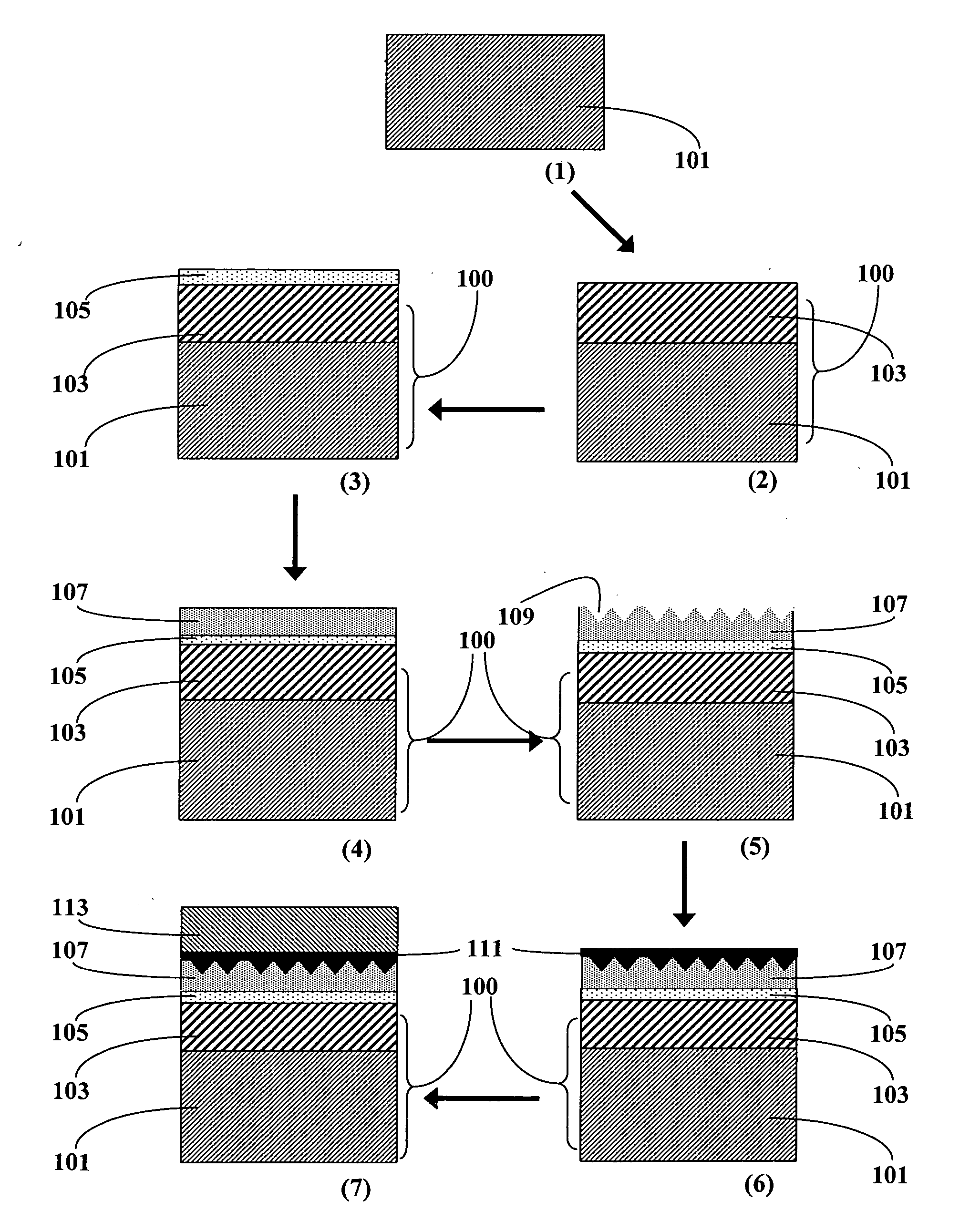
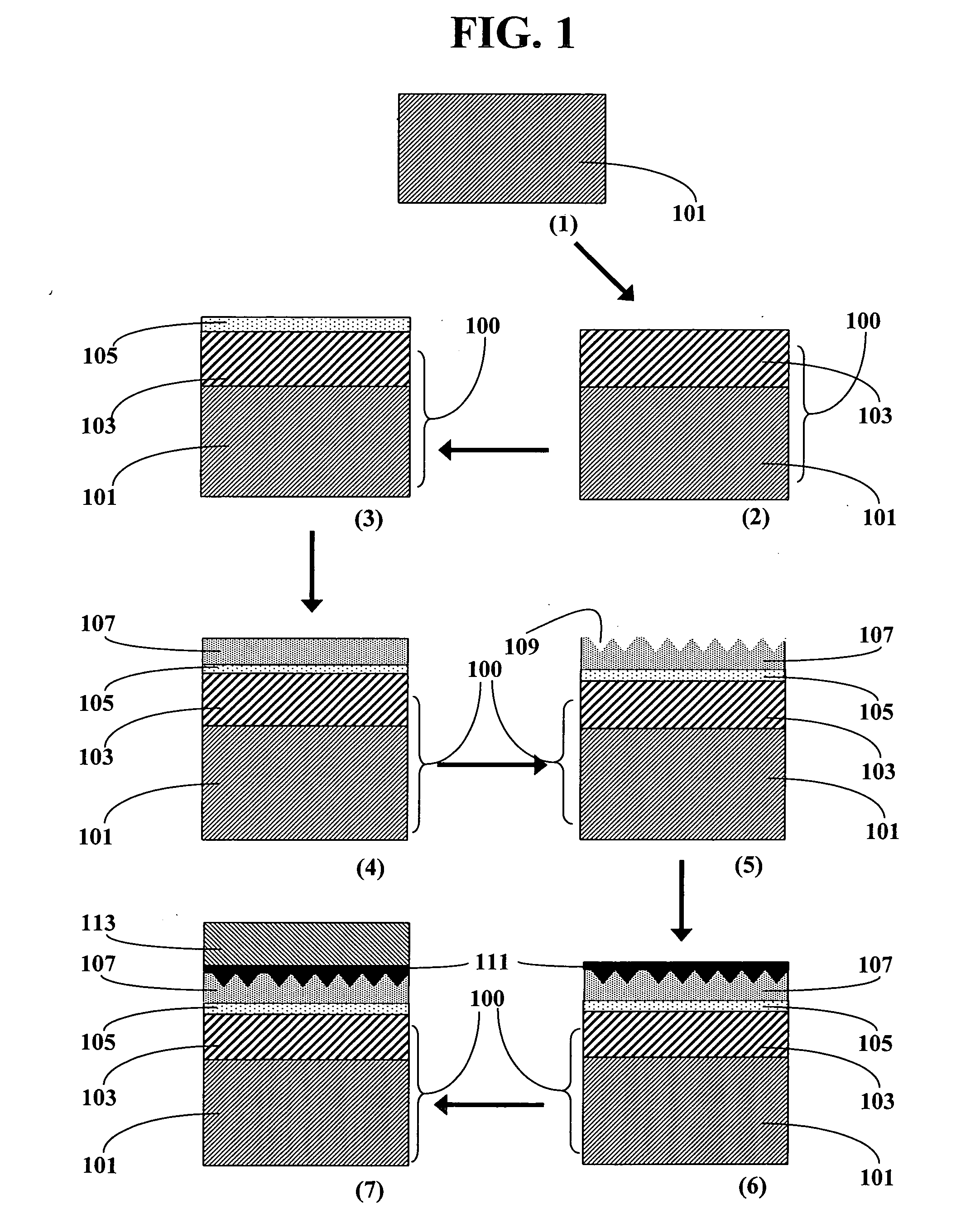
[0125] A polyurethane-urea plastic lens sold under the trade name NXT® from Intercast Europe SPA was coated with a HI-GARD® 1080 coating according to the recommended guidelines from the resin supplier. The final hardcoat was 2-3 μm thick. After surface cleaning a 100 nanometers thick SiO2 coating was vacuum-deposited using a thin chromium layer as adhesion layer deposited on the top of the hard coat prior the SiO2 deposition.

[0126] Then the coated substrate was brushed with a wheel having the appropriate shape and made of polyurethane foam. The wheel was imbibed with abrasive slurry in order to get parallels microgrooves on the surface of the coated lens.

[0127] The abrasive slurry used was a mixture of water and micron size zirconia particles in order to provide a gentle abrasive brushing. The wheel speed was 340 rpm and the pressure of about 40 g / cm2 applied for about 5 seconds. Then the grooved lens was rinsed with deionized water and dried under an infra-r...


PUM

PropertyMeasurementUnit
transparentaaaaaaaaaa
depthaaaaaaaaaa
thicknessaaaaaaaaaa

Abstract

Disclosed are novel light polarizing articles comprising a substrate, a light polarizing layer, an inorganic intermediate layer between the polarizing layer and the substrate, an optional inorganic sub-layer between the substrate and the inorganic intermediate layer, and a protective layer over the light polarizing layer, and method of making the same. Due to the presence of the inorganic intermediate layer and the optional sub-layer, adhesion of the polarizing layer is improved substantially. The light polarizing article has improved chemical, mechanical and thermal resistance. The light polarizing article can be used, for example, as ophthalmic products and in display devices.

Description

FIELD OF THE INVENTION [0001] The present invention relates to light polarizing products and method of making the same. In particular, the present invention relates to polarizing ophthalmic products comprising a light polarizing layer, a substrate and at least one adhesion layer therebetween and method of making the same. The present invention is useful in producing, for example, polarizing ophthalmic products and display products. BACKGROUND OF THE INVENTION [0002] A linear light polarizing filter allows light having electric field in a certain plane to transmit at a higher rate than light having an orthogonal electric filed. Polarizing filters have been widely used in, for example, ophthalmic products, display devices and optical communication devices. Polarizing ophthalmic lenses are interesting because they have the unique ability to selectively eliminate glare that is reflected from smooth horizontal surfaces like water and ice. [0003] Dichroic materials have been used for the ...

Claims


Application Information

Patent Timeline
Patent Type & Authority Applications(United States)
IPC IPC(8): G02F1/1335
CPCB29D11/0073G02B5/3033G02C7/12Y10T428/24264Y10T428/24479Y10T428/24537Y10T428/2457Y10T428/31504G02B5/30
Inventor BEAR, MARIE-MAUDMEYER-FREDHOLM, MICHELEHENRY, DAVIDLAFOSSE, XAVIER
Owner CORNING INC
Why Eureka
Try Eureka