Tubular sputtering target

a sputtering target and tube technology, applied in the direction of electrolysis components, vacuum evaporation coatings, coatings, etc., can solve the problems of limited heat absorption and dissipation capacity, and the inability to use sputtering targets, etc., to achieve the necessary stability and heat dissipation, improve thermal conductivity, and improve thermal conductivity.

Inactive Publication Date: 2006-07-13
W C HERAEUS GMBH
View PDF6 Cites 11 Cited by
  • Summary
  • Abstract
  • Description
  • Claims
  • Application Information

AI Technical Summary

Benefits of technology

[0005] As a result of the fact that the attachment device and/or a tube end cover is connected with the support body by positive locking or by material joining, first, the problems that arise from the otherwise necessary soldering process between the sputtering material and the support tube are avoided, and, second, the necessary mechanical strength is produced by the stabilization of the ends of the tube, and the necessary vacuum tightness is also produced by the connection by means of positive locking or material joining, especially if the target body extends almost completely over the cross section of the tube.
[0006] In particular, it is advantageous if the target body is made of metal, preferably titanium, molybdenum, niobium, chromium, tungsten, aluminum, copper, zirconium, tantalum, nickel, silver, or an alloy of at least one of these metals. Furthermore, it is advantageous if the attachment device (preferably designed as a flange) and/or the tube end cover is made of titanium, molybdenum, tungsten, chromium, aluminum, silver, nickel, zinc, copper, zirconium, vanadium, niobium, tantalum, or an alloy of at least one of these metals, since, first, these materials can be joined well with the target material, and, second, they guarantee the necessary stabilit...

Problems solved by technology

These designs, in which high-grade steel is usually used as the support tube material, have a limited capacity for heat absorption and dissipation, since the soldered con...

Method used


Image

  • Tubular sputtering target
  • Tubular sputtering target
  • Tubular sputtering target

Examples


Embodiment Construction

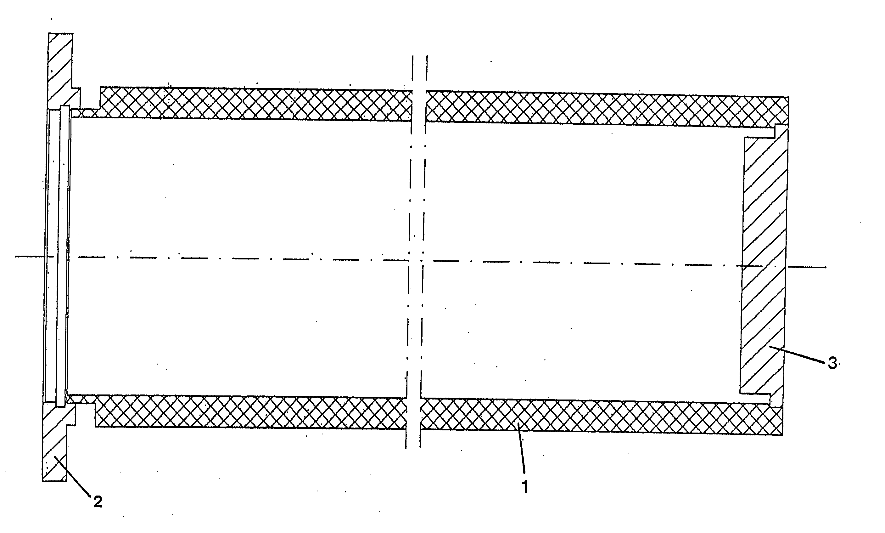
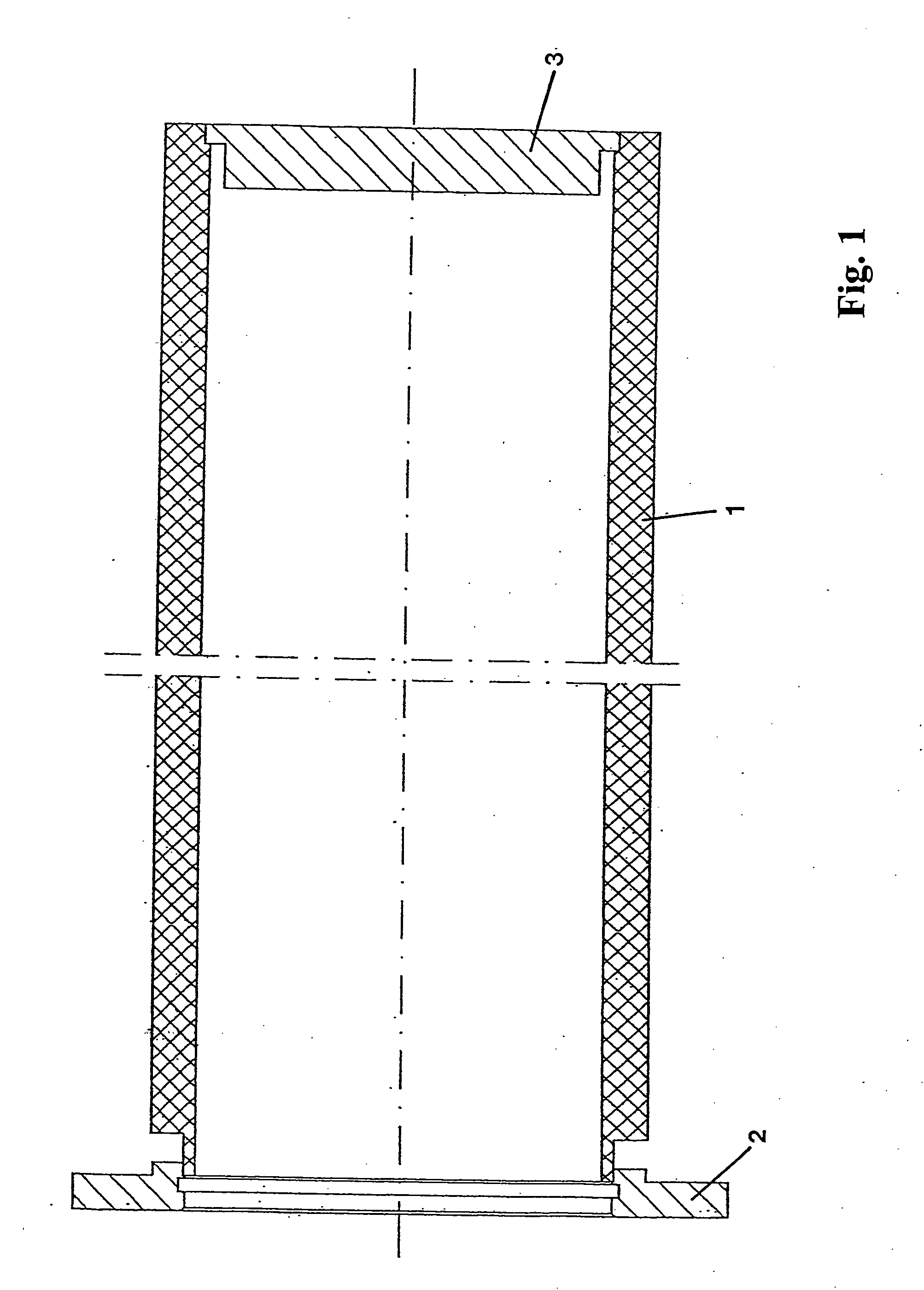
[0011] Tubular targets can be supported in the sputtering installation either at one end or at both ends. The inside of the tube is sealed vacuum-tight from the outside environment. The target / support body 1 is made of molybdenum, possibly alloyed with about 0.5 wt.% to about 5 wt. % chromium or tungsten. In the case of a tubular target supported at one end (FIG. 1), an attachment flange 2 is welded vacuum-tight to only one end of the tube by the electron beam welding process, while the other end is joined vacuum-tight with a tube end cover 3 by electron beam welding.

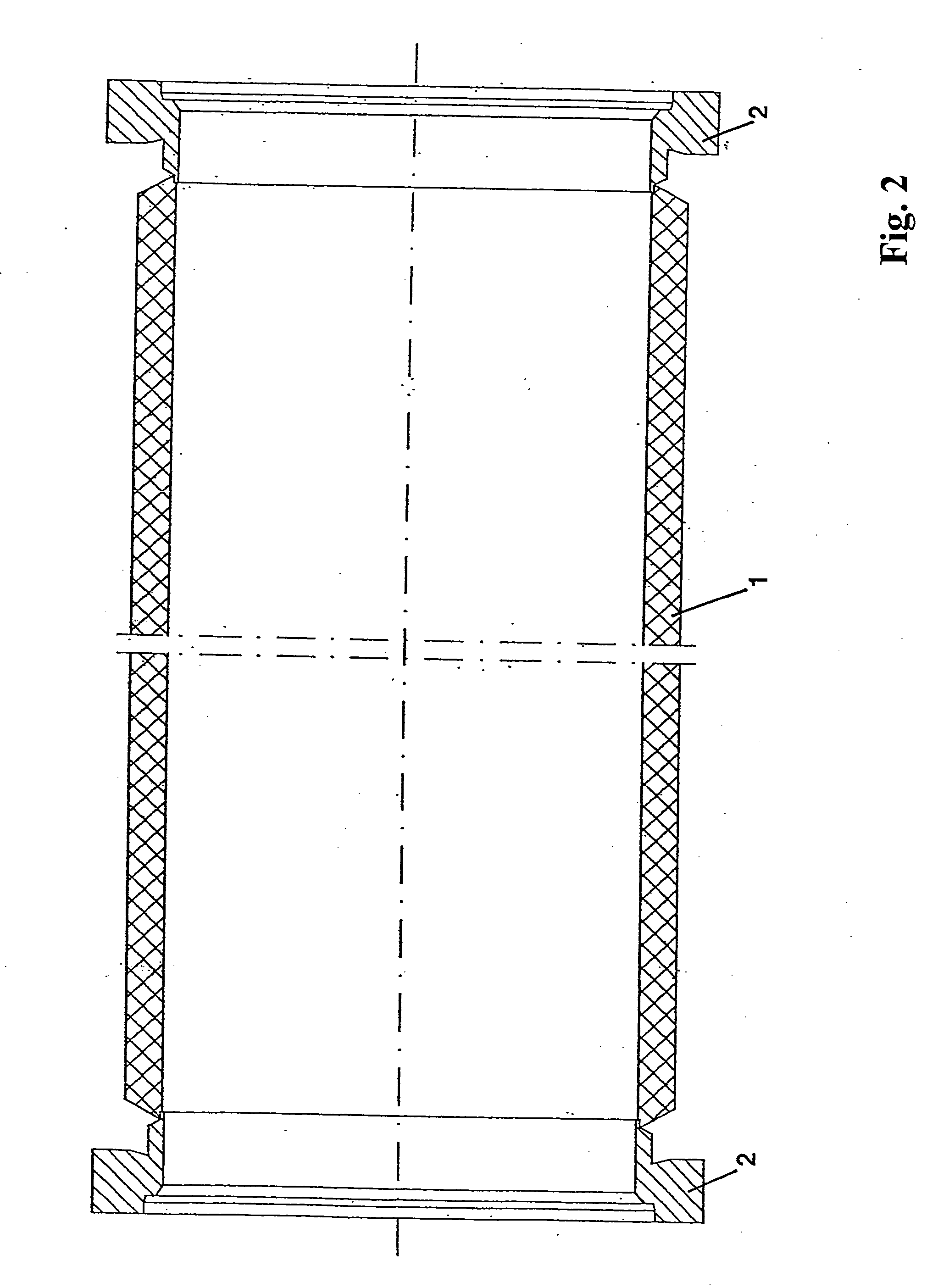
[0012] In the case of a tubular target supported at both ends (FIG. 2), and attachment flange 2 is welded onto both ends of the support body 1. Here again, the joint is vacuum-tight and is preferably produced by the electron beam welding process. The titanium alloys specified above are especially suitable materials for the tube end cover 3 or the attachment flange 2.

[0013] Molybdenum can be used, for example, as a spu...


PUM


Abstract

A tubular sputtering target with a target body and with an attachment device arranged at at least one end of the target body. The attachment device and/or an end cover are joined with the target body by material joining or positive locking.

Description

BACKGROUND OF THE INVENTION [0001] The invention concerns a tubular sputtering target with a target body and with an attachment device arranged on at least one end of the tube. [0002] Many sputtering targets of this type are known, e.g., those described in WO 97 / 15697, DE 100 43 748, and DE 100 63 383. A tubular sputtering target of this type can be formed either as a self-supporting target from the material to be sputtered or as a support tube coated with the material to be sputtered. [0003] In practice, thin coatings of molybdenum alloys for optical functional coatings are becoming increasingly important, especially in the coating or large glass surface areas and in the coating of flat screens. Coatings of this type are generally produced by sputtering, and tubular targets are being used to greater and greater extent, since they allow a higher sputtering yield and produce more uniform results. It is precisely molybdenum or molybdenum alloys (especially molybdenum-base alloys) that...

Claims


Application Information

Patent Timeline
IPC IPC(8): C23C14/00
CPCC23C14/3407H01J37/3435C23C14/34
Inventor WEIGERT, MARTINSCHULTHEIS, MARKUSSCHLOTT, MARTINSIMONS, CHRISTOPH
Owner W C HERAEUS GMBH
Why Eureka
Try Eureka