Tunable ring laser with external grating operation in a single mode

Inactive Publication Date: 2006-07-13
UNIVERSITY OF BRISTOL
View PDF3 Cites 20 Cited by
  • Summary
  • Abstract
  • Description
  • Claims
  • Application Information

AI Technical Summary

Benefits of technology

[0013] Advantageously, the tunable laser of the present invention emits precise, discrete wavelengths as determined by the cavity modes of the ring laser cavity. These modes are determined during laser manufacture and can be precisely trimmed to the accurate values required.
[0014] Further advantage is gained in that the lasing frequency tuning occurs at a high speed (potentially in the order of nanoseconds). Primarily, four factors contribute to achieving this high speed tuning. Firstly, a frequency selection means which operates at a high speed is used. Secondly, a lasing frequency lock-in time of the present invention is shorter than that of conventional tunable lasers. Lasing frequency lock-in time refers to the time for an output frequency to stabilize to a predetermined value. Thirdly, only a single control variable needs to be determined in order to set an operating frequency for the tunable laser. Fourthly, after the initial lasing frequency lock-in time, the emitted frequency is no longer affected by possible long-term transience (such as thermal drift of the frequency selection means). In this way, the time required for the tunable laser to change between different emitted frequencies is minimized and also, phase matching components (as required in some SGDBR lasers) are not necessary. Furthermore, the preferred embodiments of this invention have a ring cavity circumference of a few millimetres in length, which is considerably shorter than that of conventional tunable fibre ring devices. Laser devices of this short cavity length are capable of high speed tuning owing to the short photon lifetime in the ring cavity.

Problems solved by technology

However, Y-cavity lasers suffer from a limited side mode suppression ratio (SMSR) of less than 25 dB.
It also needs a multiple of control electrodes making tuning complicated.
The slow speed of this processing leads to an inadequate tuning speed for efficient operation of, for example, optical packet transmission systems.
This problem is further compounded by transient phenomena in the laser cavity which have relatively long decay times (such as thermal stabilizing time for the grating).
SGDBR lasers generally include phase matching components which add complexity and increase the dimensions of the device.
However, where a tuning mechanism is a part of the ring cavity and the laser cavity circumference is relatively short, then problems similar to those encountered in tunable SGDBR lasers arise.
Further, the circumference of the ring cavity determines the photon lifetime and thereby also affects the speed with which such known devices can be tuned.
Therefore, in such known devices, a tuning speed on a nanosecond timescale is not possible.)
Thirdly, only a single control variable needs to be determined in order to set an operating frequency for the tunable laser.
Fourthly, after the initial lasing frequency lock-in time, the emitted frequency is no longer affected by possible long-term transience (such as thermal drift of the frequency selection means).

Method used


Image

  • Tunable ring laser with external grating operation in a single mode
  • Tunable ring laser with external grating operation in a single mode
  • Tunable ring laser with external grating operation in a single mode

Examples


Embodiment Construction

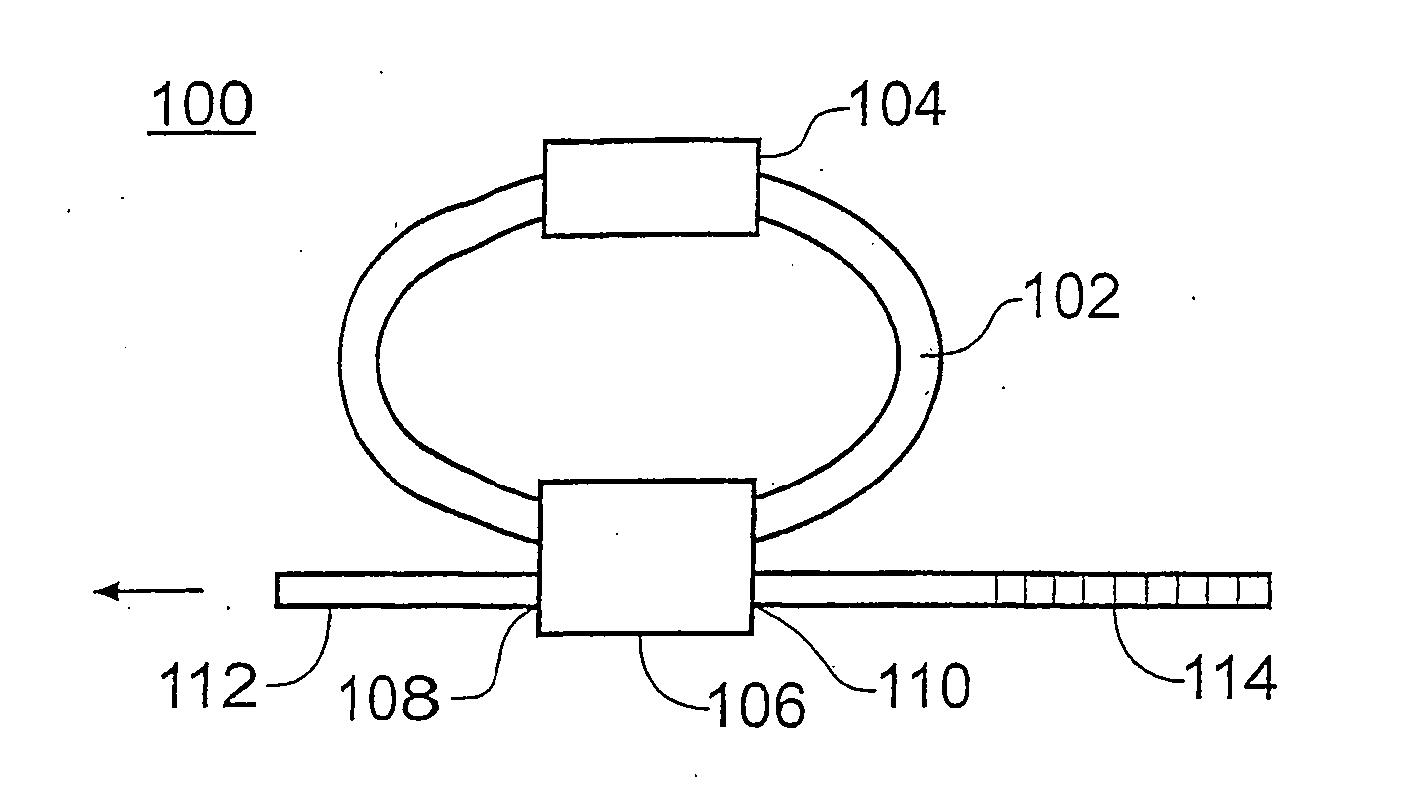
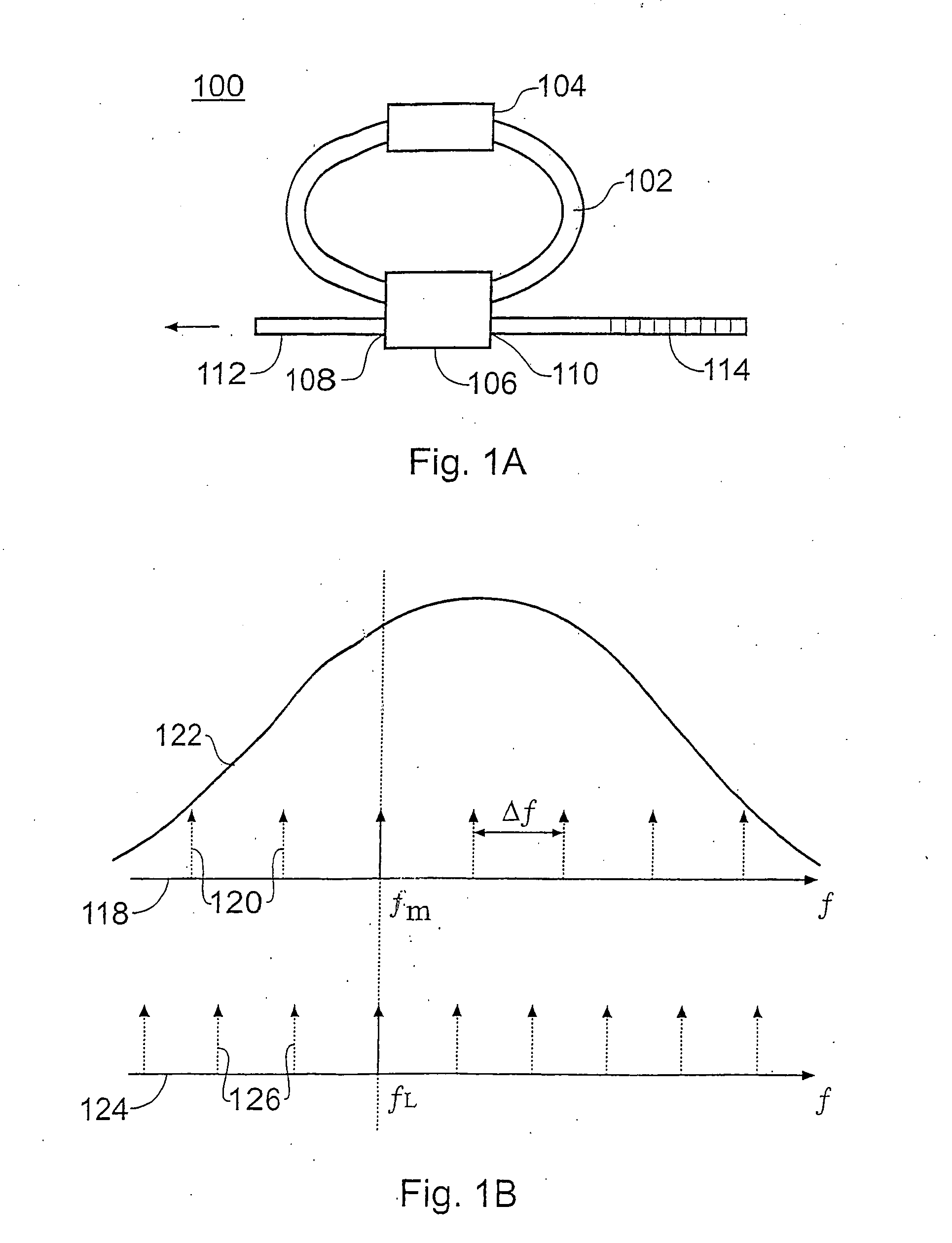
[0026] In the tunable laser 100 of FIG. 1A, a ring cavity 102 (comprised of a passive optical waveguide) and an optical gain element 104 are connected to a bi-directional optical output coupler 106. The optical output coupler 106 has a first port 108 and a second port 110. The first port 108 is coupled to an output optical fibre 112 and a second port 110 is coupled to a frequency selection means 114 (such as a grating).

[0027] In operation, the optical gain element 104 provides optical gain within a predetermined spectral range and the ring cavity 102 provides a propagation route for circulating photons at one or more frequencies within the predetermined spectral range. A laser oscillation in the ring cavity 102 occurs at a laser frequency within the gain spectral range when two operating conditions are met. First, the total optical gain at that laser frequency fL exceeds the total optical loss in the ring cavity 102, and second, the optical phase delay associated with a round trip ...


PUM


Abstract

A tunable lasing device (100) comprising a ring-shaped laser cavity (102), an optical gain element (104), a bi-directional output coupler (106) and a frequency selection means (114). The frequency selection means is generally a grating with a refractive index that determines a grating reflection frequency. Single mode laser operation is achieved where a cavity mode frequency of the ring-shaped laser cavity coincides with a grating reflection frequency. The refractive index of the grating can be modified by the injection of a variable current. In this way, the lasing frequency can be rapidly tuned between cavity mode frequencies.

Description

TECHNICAL FIELD OF THE INVENTION [0001] The present invention relates to an optoelectronic device, and in particular to a lasing device that can change an emitted wavelength at high speed. DESCRIPTION OF RELATED ART [0002] Tunable lasers are commonly used as sources in high capacity optical telecommunication systems, such as dense wavelength division multiplexing (DWDM) systems. This technique involves transmitting several optical signals via a single fibre with the optical signals having slightly differing respective wavelengths or frequency. A related technique, known as wavelength routing, involves transmitting data using precise wavelengths and rapidly interchanging between those wavelengths. Tunable lasers are also used in photonic switching systems and also find application in other fields, such as spectroscopy and optical sensing. [0003] Examples of conventional tunable semiconductor diode lasers used for optical communications are listed below. [0004] A first type is known a...

Claims


Application Information

Patent Timeline
IPC IPC(8): H01S3/083G02B6/12H01S3/063H01S3/067H01S3/08H01S5/026H01S5/065H01S5/10
CPCG02B6/12004H01S3/0635H01S3/06791H01S3/08036H01S3/083H01S5/026H01S5/0656H01S5/10H01S5/1032H01S5/1071
Inventor YU, SIYUAN
Owner UNIVERSITY OF BRISTOL
Why Eureka
Try Eureka