System and method for deploying an optical fiber in a well

a technology of optical fiber and well, applied in the field of improved methods for deploying fiber optic sensors, can solve the problems of fiber optics not being sufficiently robust for installation, optical fiber itself is hair-thin and therefore relatively delicate, and the performance of fiber optics is not sufficient, so as to prevent water penetration

Inactive Publication Date: 2006-07-13
SABEUS PHOTONICS
View PDF6 Cites 46 Cited by
  • Summary
  • Abstract
  • Description
  • Claims
  • Application Information

AI Technical Summary

Benefits of technology

[0012] The present invention is embodied in an optical fiber assembly capable of deployment down an instrumentation tube located in a well bore, comprising, in its broadest aspect, a flexible protective barrier within which is disposed an optical fiber having a core and a cladding, the protective barrier being sufficiently flexible to allow storage of the fiber assembly in a spooled condition, and having an outer diameter sized to easily fit within an instrumentation or capillary tubing though which the fiber assembly is pumped down into a well bore. The protective barrier encases the fiber assembly and prevents the permeation of water, oil, gas or other potentially corrosive substances into the fiber assembly.

Problems solved by technology

Since the optical fiber itself is hair-thin and therefore relatively delicate, special care must be taken to protect it as it is being placed in the well bore and during normal operation of the well.
A typical fiber optic is not sufficiently robust for installation in well bores where the operating temperatures may reach 250° C. In addition, the fiber optic cable frequently must be installed at lengths of up to 40,000 feet.
All of the state-of-the-art methods for installing the cable place various stresses on the fiber optic core, causing degradation in the performance of the cable, and reducing the ability of the cable to resist conditions in which the cable may be installed.
Such an interruption of well operation is commonly called an intervention, and is typically expensive, therefore to be avoided if possible.
There are several disadvantages associated with the current method of fiber deployment.
First, the fluids used to pump the fiber down the instrumentation or capillary tube may be harmful to the optical fiber and lead to failure of the optical fiber over time, especially at the elevated temperatures typically seen within a well bore.
Although various fluids have been provided that minimize degradation of the optical fiber, it is believed that all of the presently available pumping fluids will degrade the fiber over time to the extent that the optical fiber is eventually rendered unusable and requires replacement.
Although pumping the fiber out of the well, and deploying a new fiber is possible, as described above, the procedure is time consuming and expensive even though the well-continues to operate during the removal and re-deployment of the fiber.
Further, it is well known that any moisture (water) present in the instrumentation or capillary tube will also seriously attack the integrity of the optical fiber at elevated temperatures.
In addition, hydrogen gas, normally found in many oil and gas wells, tends to seep into the instrumentation or capillary tubing over time.
The end result of the above described processes is that the optical fiber fails regularly when subjected to high temperatures within the well bore, sometimes in a matter of days, and has to be replaced.
Although replacement of the fiber does not require an intervention, the fiber costs tens of thousands of dollars, and special equipment, personnel, and the like have to be brought to the well site, which may be located in an isolated area, to remove the damaged fiber and deploy a new fiber.

Method used


Image

  • System and method for deploying an optical fiber in a well
  • System and method for deploying an optical fiber in a well
  • System and method for deploying an optical fiber in a well

Examples


Embodiment Construction

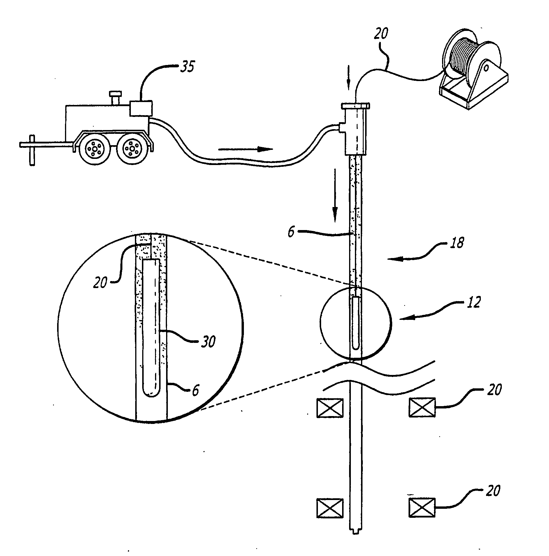
[0024] The present invention is well suited for use within a high temperature, hazardous environment. The device of the invention is suitable for use in a caustic, high temperature and pressure environment, such as the environment found downhole in an oil or gas well. Well bores range in depth from several hundred to several thousand feet. Consequently, hydrostatic pressure within a deep bore, in addition to high well head pressures caused by gas production, can be quite large and can reach and often exceed 70 MPa (approximately 10,000 pounds per square inch). Ambient well temperatures on the order of 200° C. (392° F.) are not uncommon. In addition, oil wells typically contain highly corrosive hydrogen sulfide and carbon dioxide gases. These harsh environmental conditions dictate that fiber optic cable and equipment must be enclosed within protective tubing or barriers.

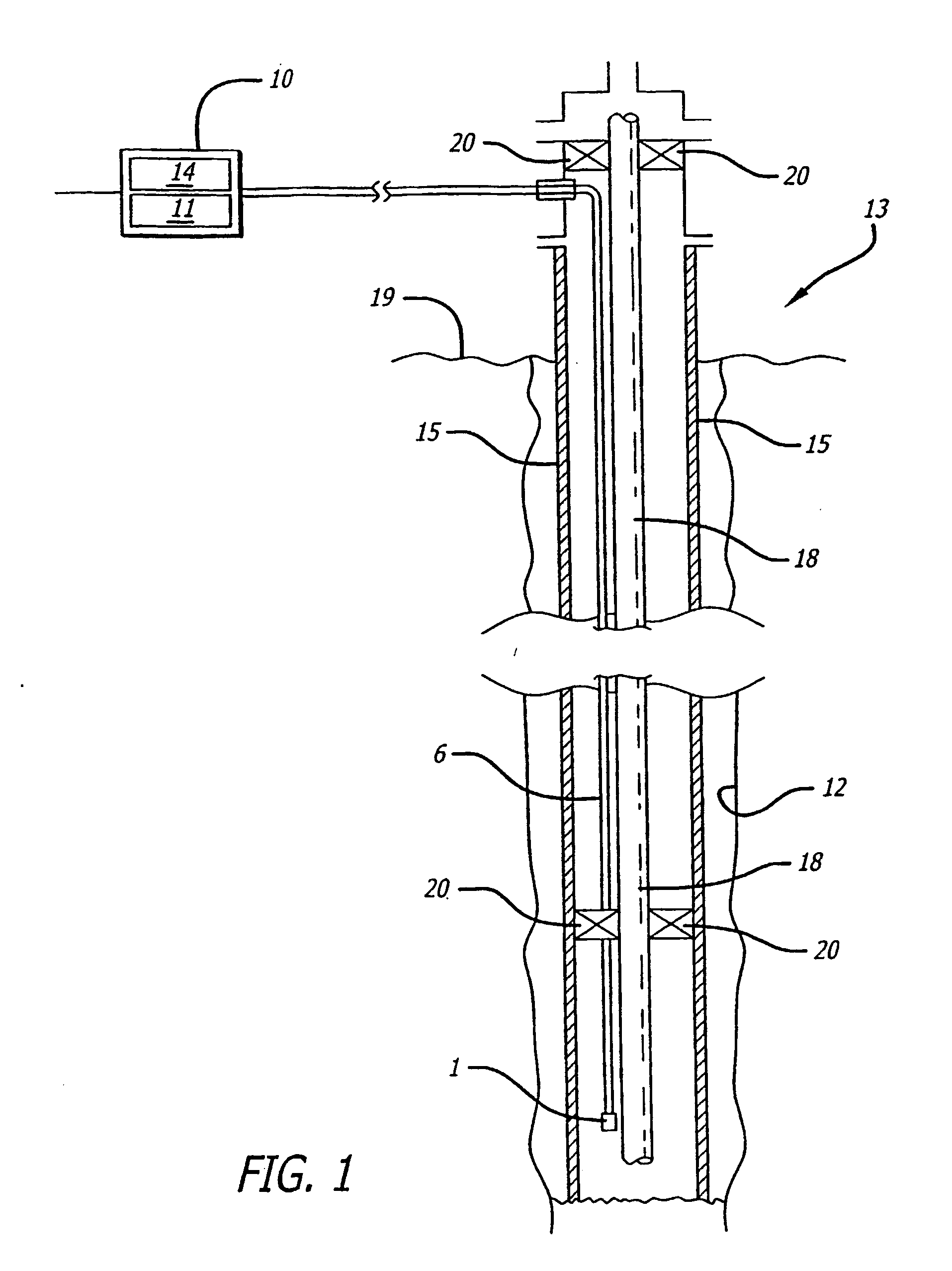
[0025] Referring now to FIG. 1, a typical well bore having an instrumentation tubing placed therein is depicted. A...


PUM


Abstract

A fiber optic sensor assembly capable of deployment down an instrumentation tube located in a well bore, including a flexible protective tube having a lumen encasing an optical fiber having a core portion and a cladding portion disposed within the flexible tube. The flexible protective tube protects the optical fiber from the oil, water or hydrogen gas within the well bore. A method of deploying the optical fiber down the well bore, is also provided. An optical fiber having a core and a cladding surrounded by the flexible protective tubing is deployed into the lumen of a tube disposed within the well bore by pumping a high pressure fluid into the lumen of the tube, thereby causing the deployment of the optical fiber down the well bore. The protective tubing is impermeable of hydrogen and other corrosive materials.

Description

CROSS-REFERENCE TO RELATED APPLICATION [0001] This application claims the benefit of priority to U.S. Provisional Application No. 60 / 440,255, filed Jan. 15, 2003, the subject matter of which is incorporated herein in its entirety.BACKGROUND OF THE INVENTION [0002] 1. Field of the Invention [0003] The invention relates to an improved method for deploying fiber optic sensors into hostile environments such as down well bores. [0004] 2. General Background and State of the Art [0005] Fiber optic sensors are beginning to be used in oil and gas fields to sense parameters of interest to operators such as temperature and pressure down well bores. The primary advantages of fiber optic sensors include the complete elimination of electronics from the well bore as well as the sensors small size and weight. The optical fiber itself serves as both the sensor and the telemetry path. Since the optical fiber itself is hair-thin and therefore relatively delicate, special care must be taken to protect ...

Claims


Application Information

Patent Timeline
Patent Type & Authority Applications(United States)
IPC IPC(8): G02B6/44E21B23/08E21B47/12
CPCE21B23/08E21B23/14E21B47/123G02B6/4464G02B6/4492E21B47/135G02B6/44382G02B6/52
Inventor BOWKER, THOMASGOLDNER, ERICLSHAW, MICHAEL
Owner SABEUS PHOTONICS
Why Eureka
Try Eureka