Method of automated prismatic electrochemical cells production and method of the cell assembly and construction

a technology of prismatic electrochemical cells and assembly methods, which is applied in the direction of cell components, final product manufacturing, sustainable manufacturing/processing, etc., can solve the problems of reducing energy density, increasing cell resistance, and reducing energy density, so as to improve energy density, power density, and heat resistance. , the effect of improving the efficiency of the process

Inactive Publication Date: 2006-07-20
KEJHA JOSEPH B +2
View PDF17 Cites 40 Cited by
  • Summary
  • Abstract
  • Description
  • Claims
  • Application Information

AI Technical Summary

Benefits of technology

[0026] The principal object of this invention is to provide a more reliable electrochemical cell construction, which has a superior energy density, power density, heat resistance and easier automated assembly over the prior art.
[0027] Another object of this invention is to provide simpler, less costly, automated production method of electrochemical devices over the prior art.

Problems solved by technology

This separator is too soft and must be thick to prevent shorts, which decreases the energy density.
However, all these methods add a thickness to the cell due to additional layers, and partially close, or restrict the separator pores, which increase the cell resistance, and decrease the energy density.
The entire prior art methods above are very labor intensive with many steps, and therefore costly.
The hard casings are usually heavy and the prismatic battery cells or capacitors have size limitations, due to limited stiffness of the casing and its ability to maintain pressure on the stack.
The solid metal foil current collectors seal the surface of the electrodes and restrict soaking of the cell by the electrolyte, and the soaking must be therefore done under vacuum, which is costly.
Also lead-acid batteries, such as Panasonic lead-acid gelled prismatic batteries have stacked thick electrode plates, which assembly is difficult to automate.
Automated production of liquid electrolyte prismatic, or rolled electrochemical devices requires complex and expensive robotic machinery for handling of the loose components and assemblies.
Prior art lithium polymer cells production methods and cell structures require, or result in having a relatively thick separator, due to the soft polymer, non-uniform coating, and / or thick net, which decreases the energy density of the cells, and makes them thus non-competitive in this respect with the liquid electrolyte prismatic cells having thin and tough Celgard separator.
However, the non-welded prismatic and rolled cells have heavy casings.
Both patents utilize the plasticized polymeric matrix of the electrodes for bonding the electrodes to the polyolefin separator, and both patents are limited to using only polyolefin separators, due to their thermal shut-down feature for the described safety reason.
However, it has been found that the thermal shut down feature is undesirable because it causes a catastrophic battery failure, when the cells are connected in series.

Method used


Image

  • Method of automated prismatic electrochemical cells production and method of the cell assembly and construction
  • Method of automated prismatic electrochemical cells production and method of the cell assembly and construction
  • Method of automated prismatic electrochemical cells production and method of the cell assembly and construction

Examples


example # 1 (

EXAMPLE #1 (NON-AQUEOUS BATTERY SINGLE CELL PREPARATION)

[0049] a. Several cathode current collectors were cut into section from aluminum expanded micro grid (Exmet Corp.), and surface treated by well known electrically conductive coating(Acheson EB-012). Cathode slurry of desired viscosity with PVDF homo polymer binder and without any plasticizer was prepared according to the same patent application, containing LiCoO2 as the active material, and a carbon. The current collectors were partially, vertically hand dipped into the slurry, then slowly pulled upward, suspended on a rack, and then vacuum dried in vacuum oven at approximately 100° C. for 2 hours.

[0050] b. Similarly, several anode current collectors were cut into sections from copper expanded micro grid (Exmet Corp.), surface treated, as described in our patent application Ser. No. 09 / 911,036, identically hand dip coated by anode slurry of desired viscosity and without any plasticizer, containing mesocarbon microbeads (MCMB) ...

example # 2 (

EXAMPLE #2 (NON-AGUEOUS BATTERY SINGLE CELL PREPARATION)

[0057] a. Metal microgrids of both electrodes, as described in the Example #1 were identically cut, treated and dip-coated, except at this time by well known plasticized active materials slurries of desired viscosity with PVDF / HFP binder as described in prior art patents, but the slurries contained propylene carbonate (PC) instead of the conventional dibutyl phalate (DBP). The coated grids were suspended and dried in air at room temperature, cut into identical sections, and calendared, as described in the Example #1.

[0058] b. Untreated, dry Gore Excellerator microporous PTFE separator, as described in the Example #1, step “d” was identically prepared.

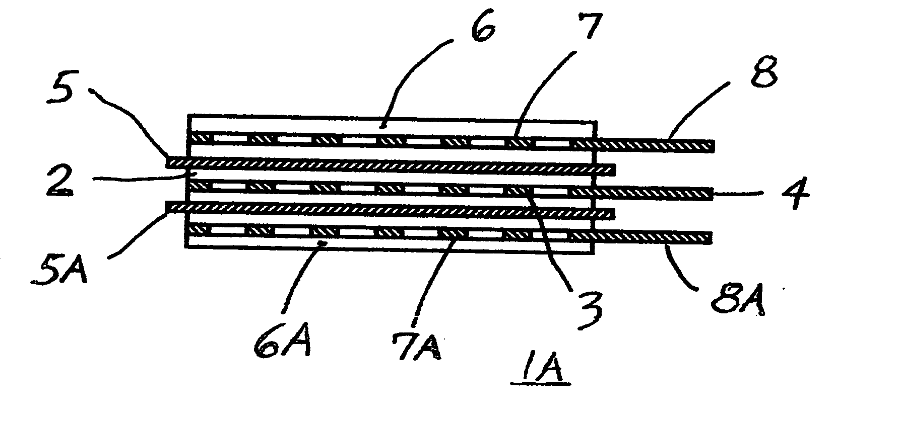
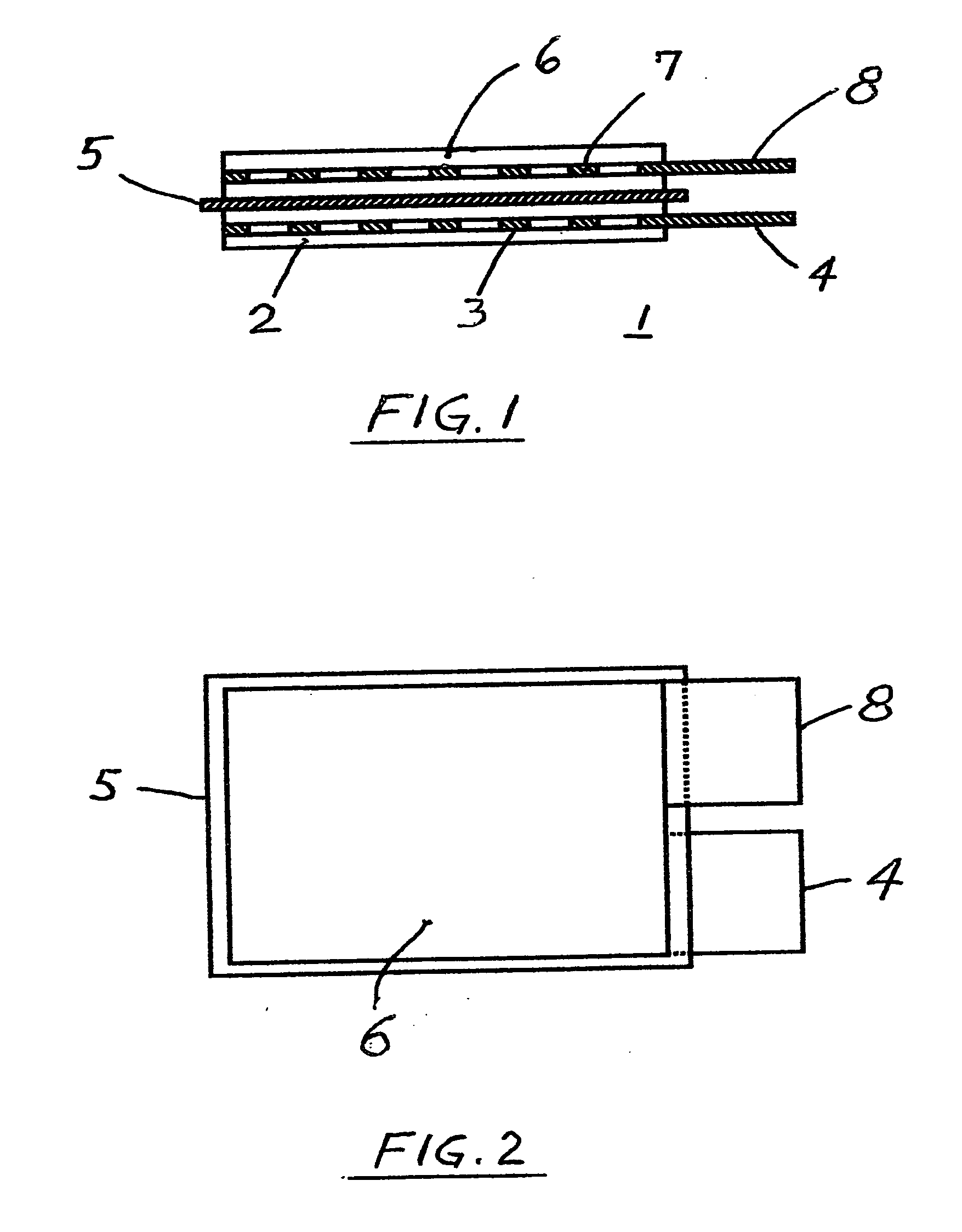
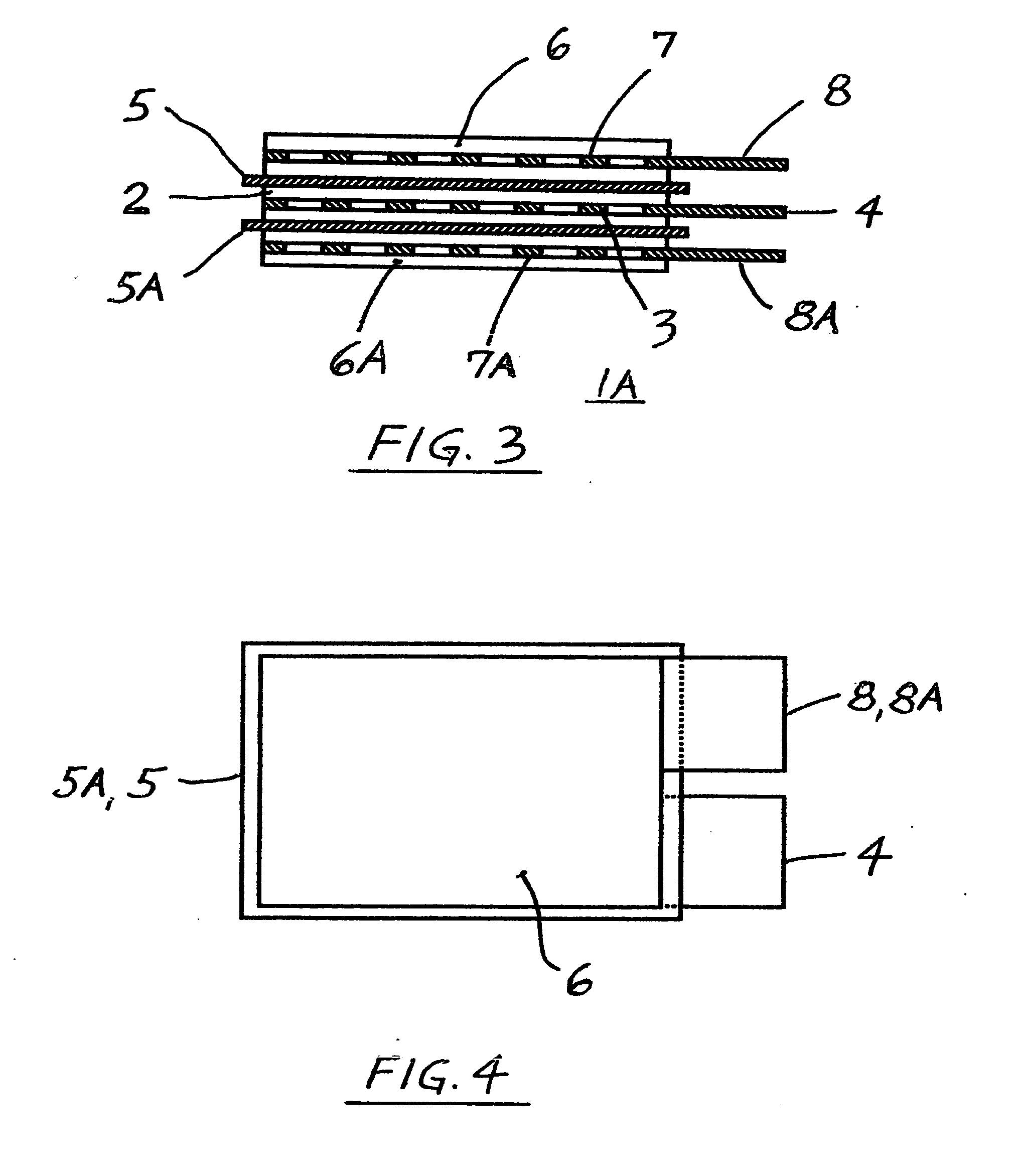
[0059] c. The separator from the step “b” of this Example #2 was sandwiched between the plasticized, matching electrodes in overlying relation, as shown in FIGS. 1 and 2, and was heat welded and / or bonded to the electrodes, similarly as described in the Example #1, and without da...

example # 3 (

EXAMPLE #3 (ULTRACAPACITOR SINGLE CELL PREPARATION)

[0061] a. Several electrodes' current collectors were cut into sections from aluminum expanded micro grid (Exmet Corp.) and surface treated by well known electrically conductive coating as manufactured by Acheson. Electrodes' active coating slurry of desired viscosity with PVDF homo polymer binder and without any plasticizer was prepared as described in our patent application Ser. No. 09 / 911,036 for anode, except the MCMBs of the same % WT. were replaced by activated carbon obtained from TDA Research, Inc. The current collectors were partially, vertically hand dipped into the slurry, then slowly pulled upward, suspended on a rack and then vacuum dried for 2 hours.

[0062] b. All above electrodes were then cut into the same size section, (having uncoated terminal tabs as shown in FIG. 2), weighed and marked and kept in a group.

[0063] c. Untreated, dry Gore Excellerator, microporous 12 microns thin PTFE separator (as sold for use in l...


PUM

PropertyMeasurementUnit
boiling pointaaaaaaaaaa
temperatureaaaaaaaaaa

Abstract

The present invention pertains to electrochemical devices having a thin micro porous polytetrafluoroethylene separator bonded to their porous electrodes without special treatment of the separator and without additional adhesive layers. Structures of superior high energy density and power density are disclosed herein, as well as the methods of their assembly and automated production.

Description

CROSS REFERENCE TO RELATED DOCUMENTS [0001] This Application is a continuation in part of the Application of Joseph B. Kejha at al., Ser. No. 10 / 119 / 220 filed on Apr. 9, 2002, and entitled “Method of Automated Hybrid Lithium-Ion Cells Production and Method of the Cell Assembly and Construction”, which is a continuation in part of the application of Joseph B. Kejha at al. Ser. No. 09 / 911,036, filed Jul. 23, 2001 and entitled “Manufacturing Method and Structure of Electrodes for Lithium-Based El. Chemical Devices. The subject matter of the invention is shown and described in the Disclosure Document of Joseph B. Kejha, Ser. No. 490,145 filed on Mar. 8, 2001, and entitled “Automated Lithium-Polymer Cells Production and Method of Cell Assembly and Construction.”, and in the Disclosure Document of Joseph B. Kejha, Ser. No. 583,446 filed on Aug. 2, 2005 and entitled “Improved Prismatic Capacitors, Ultracapacitors and Lead-Polymer Cells, their Hybrids and Low Cost Assembly Method.”BACKGROUN...

Claims


Application Information

Patent Timeline
Patent Type & Authority Applications(United States)
IPC IPC(8): H01M2/16H01M10/04H01M4/58H01M4/62H01G9/02H01G9/00H01G9/155H01M4/13H01M4/74H01M10/0525H01M10/0585H01M10/36H01M50/426H01M50/491
CPCH01M2/1673Y10T29/49115H01M4/622H01M4/625H01M4/661H01M4/72H01M4/74H01M10/04H01M10/0436H01M10/0525H01M10/058H01M10/0585Y02E60/122Y02E60/13H01G9/02H01M2/1653H01G11/28H01G11/32H01G11/52Y10T29/49114H01M4/13Y02E60/10H01M50/46Y02P70/50H01M50/491H01M50/426H01G9/00
Inventor KEJHA, JOSEPH B.CHUA, DAVIDLIN, HSIU-PING
Owner KEJHA JOSEPH B
Why Eureka
Try Eureka