Extreme UV radiation source device and method for eliminating debris which forms within the device

a radiation source and radiation source technology, applied in the field of extreme uv radiation source devices and methods, can solve the problems forming large amounts of debris, and not adequately vaporizing before exceeding 2000° c, and achieve the effect of reducing the performance of the device and high efficiency

Active Publication Date: 2006-07-27
USHIO DENKI KK
View PDF9 Cites 76 Cited by
  • Summary
  • Abstract
  • Description
  • Claims
  • Application Information

AI Technical Summary

Benefits of technology

[0029] The invention was devised to eliminate the above described disadvantages in the prior art. Thus, a primary object of the invention is to devise an extreme UV radiation source device in which debris as a result of the radiating fuel, such as tin or the like, is stopped from depositing and the reduction of the performance of the de

Problems solved by technology

Tin has the property that it does not adequately vaporize before exceeding 2000° C. Therefore, conventionally, tin is supplied to the plasma production area by vaporization of tin by laser irradiation, by self-heating of a tin supply source by a discharge and by similar methods.
Accordingly, when a high density and high temperature plasma is being produced by heating or excitation, there is the disadvantage that a large amount of debris is formed as a result of the tin.
This degrades the performance of the device.
Since its path is complicated, it often passes through the debris trap.
As a result of the vigorous research and experiments of the inventors, it was found that even by supplying SnH4 as the radiating fuel supply material to the producing area for a high density and high temperature plasma within the EUV radiation source device, deposition of tin and/or a tin compound (for examp

Method used


Image

  • Extreme UV radiation source device and method for eliminating debris which forms within the device
  • Extreme UV radiation source device and method for eliminating debris which forms within the device
  • Extreme UV radiation source device and method for eliminating debris which forms within the device

Examples


first embodiment

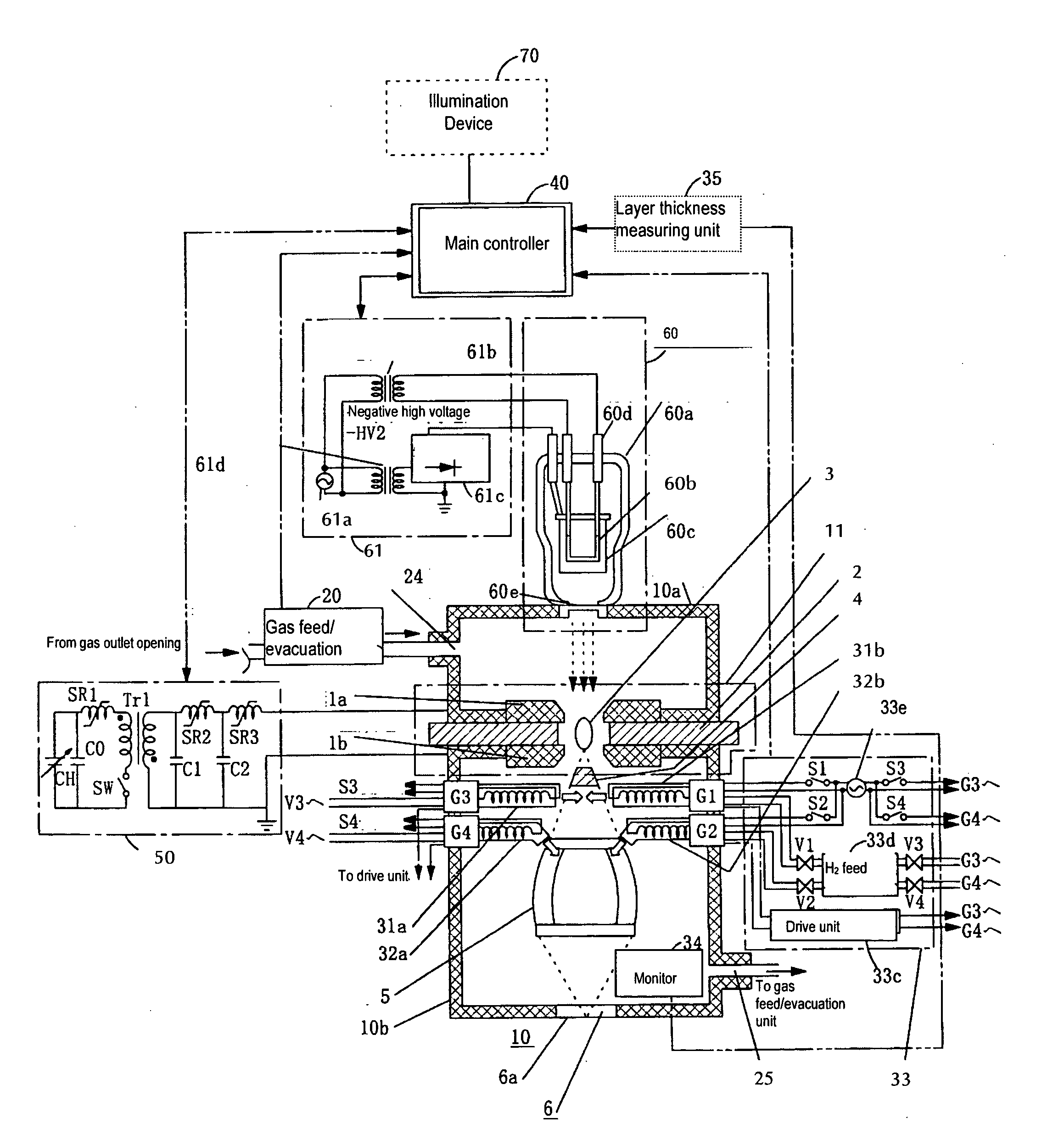
[0255]FIG. 5 schematically shows the specific arrangement of a first embodiment of the EUV radiation source according to the invention, in which a means for producing hydrogen radicals has been installed. FIG. 5 shows the same light source device as the EUV radiation source device of the DPP type which is shown in FIG. 3. The same parts as in FIG. 3 are provided with the same reference numbers as in FIG. 3 and are no longer further described.

[0256] As shown in FIG. 5, in a chamber 10 as the discharge vessel, a first ring-like main discharge electrode 1a (cathode) and a second ring like main discharge electrode 1b (anode) are arranged such that they clamp a ring-like insulating material 2. The electrodes 1a, 1b and the insulating material 2 are arranged, as was described above, such that the respective through openings are essentially coaxial. If a discharge forms between the electrodes 1a, 1b, high density and high temperature plasma is produced in this through opening or in its vi...

second exemplary embodiment

(2) Second Exemplary Embodiment

[0325]FIG. 10 shows the specific arrangement of a second exemplary embodiment of the EUV radiation source in accordance with the invention in which a means for producing hydrogen radicals has been installed. Here, as in FIG. 3 and FIG. 5, an EUV radiation source device of the DPP type is shown. The same parts as in FIGS. 3 & 5 are provided with the same reference numbers and are not further described.

[0326] In this embodiment, unlike the arrangement shown in FIG. 5 according to the first embodiment, there are radical producing parts 32c, 32d on the EUV radiation exit side of the EUV focusing mirror 5.

[0327] The radical producing parts 32c, 32d are arranged on the EUV radiation exit side of the EUV focusing mirror 5 such that the emission direction of the hydrogen radicals is opposite the surface of the EUV focusing mirror 5 on which the tin and / or tin compound has deposited. The radical producing parts 32c, 32d, like the radical producing parts 32a, ...

third embodiment

(3) Third Embodiment

[0339]FIG. 11 shows the specific arrangement of a third exemplary embodiment of the EUV radiation source of the invention in which a means for producing hydrogen radicals has been installed. Here, as in FIGS. 3 & 5, an EUV radiation source device of the DPP type is shown. The same parts as in FIGS. 3 & 5 are provided with the same reference numbers and are not further described.

[0340] In this embodiment, the following are done:

[0341] The radial arm 5c, which is arranged for supporting the mirror 5a of the EUV focusing mirror 5 which shown above in FIG. 6, is formed as a cavity;

[0342] there are several openings in the radial arms 5c (FIGS. 12(a) &12(b));

[0343] the radial arms 5c are coupled to the radical producing parts;

[0344] hydrogen radicals are routed into the cavity of the radial arms 5c; and

[0345] the hydrogen radicals from the above described openings are supplied to the reflection surface of the EUV focusing mirror 5.

[0346] As was described above, ...


PUM


Abstract

To suppress the adherence of debris as a result of a radiating fuel, such as tin or the like, within a vessel for forming high density and high temperature plasma of an extreme UV radiation source device, and to eliminate deposited tin and/or tin compounds with high efficiency, hydrogen radical producing parts are provided in the vessel; and hydrogen radicals are produced in the vessel so that deposition of tin and/or a tin compound is suppressed in the area with a low temperature of the device, such as a focusing mirror or the like, and the deposited tin and/or tin compound is eliminated.

Description

BACKGROUND OF THE INVENTION [0001] 1. Field of the Invention [0002] The invention relates to an extreme UV radiation source device which emits extreme UV radiation, and a process for eliminating debris which forms in an extreme UV radiation source device. The invention relates especially to an extreme UV radiation source device in which the effort is made to prolong its service life by introducing hydrogen radicals, and a process for eliminating contaminations. [0003] 2. Description of the Prior Art [0004] According to the miniaturization and increased integration of an integrated semiconductor circuit, an increase of resolution is required in a projection exposure tool when it is being manufactured. To meet this requirement, the wavelengths of the exposure light source are being increasingly shortened. An extreme UV radiation source device (EUV radiation source device) which emits extreme UV radiation (hereinafter also called EUV (extreme ultraviolet) radiation) with wavelengths fr...

Claims


Application Information

Patent Timeline
IPC IPC(8): H05G2/00G21G4/00H01J35/00
CPCB82Y10/00G03F7/70033G03F7/70916H05G2/001
Inventor INOUE, MASAKIYABUTA, HIRONOBUSUMITOMO, TAKUSEKI, KYOHEIYOSHIOKA, MASAKI
Owner USHIO DENKI KK
Why Eureka
Try Eureka