[0009] The human detection and
tracking system disclosed herein has the ability to overcome the problems of foreground segmentation and
false alarm reduction in real-time when integrated into a DVR.
[0010] The current invention addresses deficiencies in the prior art by implementing a shadow
detection filter in the background segmentation stage of the human and object tracking process. The shadow filter performs an analysis of colour variation to normalize for colour change due to shadows, and performs
edge detection to prevent
false alarm shadow removal. One aspect of the invention combines a shadow filter, a size filter and a morphologic filter with a 1-Gaussian distribution analysis of the image, to achieve a background segmentation step with performance comparable to that of a mixed Gaussian analysis, but requiring far fewer computations of the mixed Gaussian analysis.
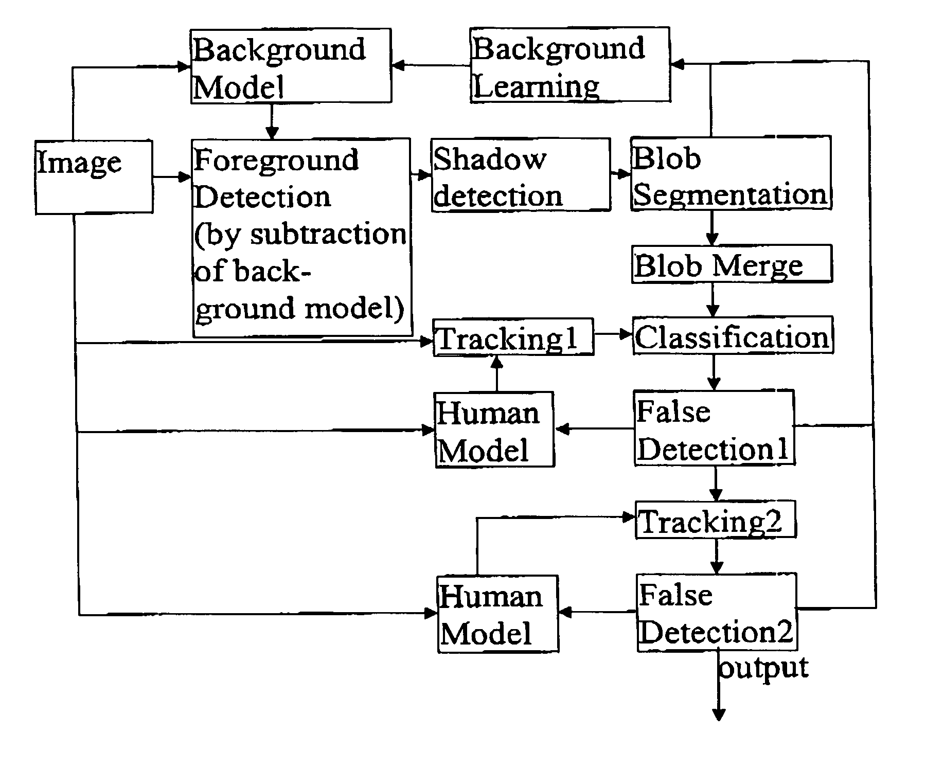
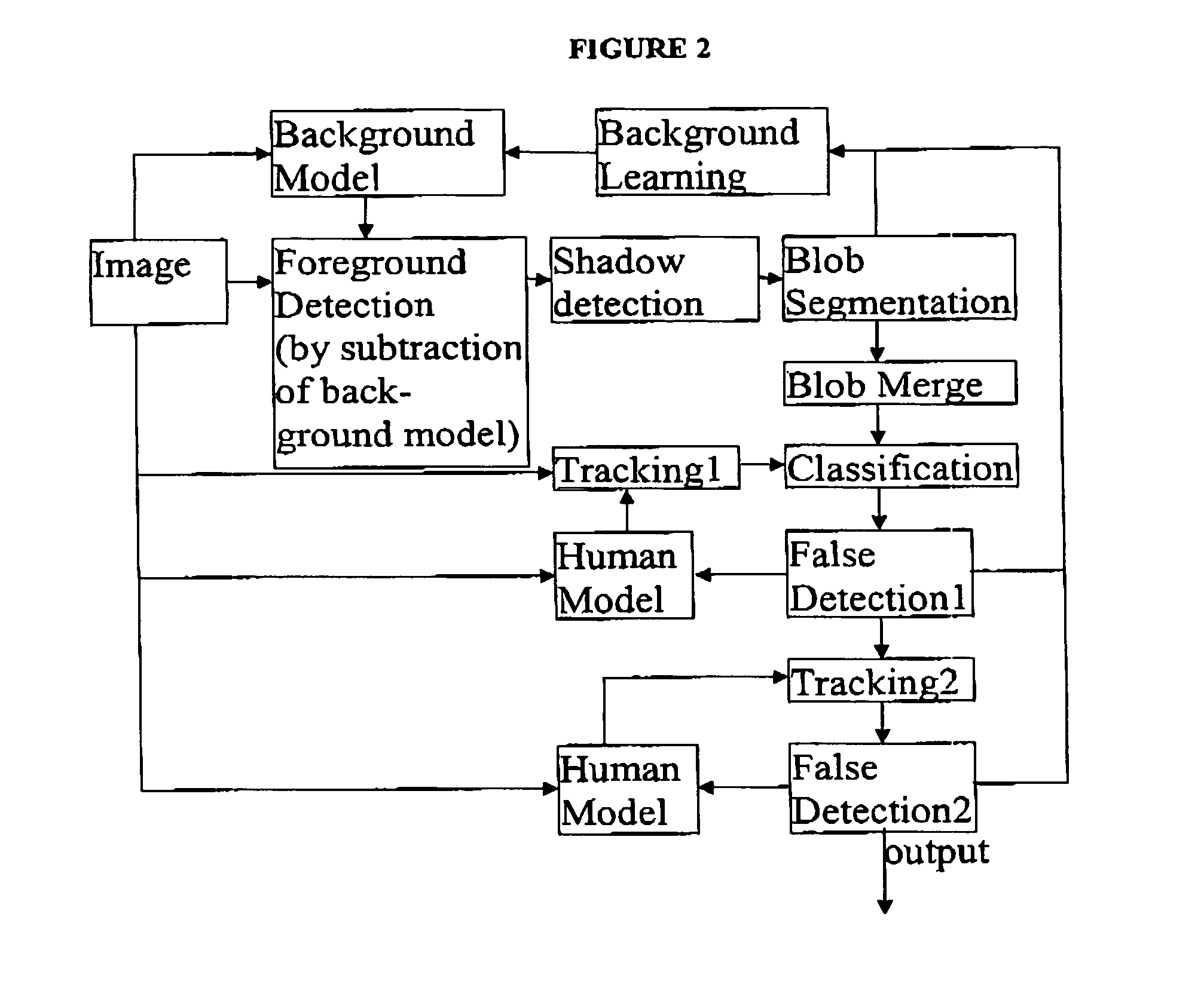
[0011] The steps in the human and object tracking process are background segmentation, subtraction of
background image to reveal foreground image,
noise filtering on foreground image, and
blob detection. “Blob” is a term of art used to describe a foreground image segment representing an item of interest, which may be human, animal, or anything not resolved into the background. Once the blob has been created (i.e. once an item of interest detected), the invention may implement various
video processing features adapted to perform using less processor power than existing designs. As one of the technical improvements of the current invention, a trained
library of vectors relating to characteristic ratios in the blob can be used to identify whether the blob represents either a human or a non-human item. Human can be efficiently identified by automated measurement of similar ratios of an object moving within the video
stream, and comparison of the measured ratios with the trained
library of
characteristic ratio vectors is an efficient implementation of the human identification feature. As a second improvement, a
record of the positions of the blob through a series of frame in the video
stream can be tracked without a further need for background segmentation on the entire image. As a third improvement, a vector based human recognition method is applied to a blob identified as human. The sub-image or blob containing an identified human can be further analysed by the DVR to perform automated human recognition based on a continually generated
codebook of possible subject humans, whose
characteristic ratio vectors have been recorded.
[0012] The analysis of the sub-image or blob, as opposed to the original video streams, saves
processing power, so that the features of behaviour analysis, movement records, and tripwire alarm status can be operated simultaneously and in real time.
[0014] The importance of real time monitoring of such events is an important improvement of the current
system over existing systems and has real economic value. The computation savings in the background segmentation step allow for loitering, theft, left baggage, unauthorized access, face recognition, human recognition, and unusual conduct to all be monitored automatically by the DVR in real time after the initialization phase performed on the image. In a preferred embodiment, the background segmentation phase is performed every 30 seconds for a static camera. Recalibrating the
background image allows the processor to save time by not actively tracking stopped objects until they have begun to move again. The
system is able to automatically determine whether objects or humans have been incorporated into the background, and an appropriate counter or flag is set related to the object or loiterer. Objects which should not become part of the moving foreground image can be flagged as stolen. The addition of the shadow filter reduces the number of false positives (false alarms) without unduly increasing the number of false negatives (missed detections). Since the DVR is a fully integrated solution, the results of each detected event can be programmed to automatically call for a live response.
[0015] The human object recognition and
tracking system of the current invention also employs a recursive “learning”
algorithm which allows the system to quickly reduce the number of false alarms triggered, without significantly impacting the number of false negatives. Model based human recognition analyzes the shape of an object and distinguishes people from other objects based on criteria discussed in greater detail below. In order to recognize human beings, a
codebook of potential shapes is used to model the shape of a person. A
distortion sensitive competitive learning
algorithm is used to design the codebook. A pre-populated codebook may be used to initialize the system, and as the system operates in a given environment, the codebook is improved through operation.

