Optical transmission system, optical repeater, and optical transmission method

a transmission system and optical repeater technology, applied in electromagnetic repeaters, multiplex communication, instruments, etc., can solve the problems of reducing the sn ratio of the entire transmission system, and affecting the transmission quality

Inactive Publication Date: 2006-08-10
FUJITSU LTD
View PDF14 Cites 10 Cited by
  • Summary
  • Abstract
  • Description
  • Claims
  • Application Information

AI Technical Summary

Benefits of technology

[0024] In this manner, the interval between the repeater distances for amplifying a short wavelength band included in wavelength-multiplexed light can be made practically shorter than the interval between the repeater distances for amplifying the light in a long wavelength band. Therefore, both transmission-line loss in the short wavelength band and loss due to Stimulated Raman Scattering can be reduced.
[0026] In this manner, at the input of the optical repeater or the end office, an output difference with a signal light having other wavelengths becomes smaller and the optical SN ratio is improved. Even at a short wavelength like a specific wavelength band, transmission quality fit for use can be maintained.
[0032] In this manner, an optical auxiliary repeater for amplifying light present on the short wavelength side of a working wavelength band can be provided between an end office and an optical repeater for amplifying all wavelengths, or between optical repeaters. The optical SN ratio of the light on the short wavelength side is prevented from being degraded by Stimulated Raman Scattering. In addition, the optical SN ratio of the entire transmission system can be improved.

Problems solved by technology

If the light power (hereinafter referred to as power) of transmission light to be output from an end office or optical repeater is made too great by the pre-emphasis, a signal light with a plurality of wavelengths will increase the influence of a nonlinear optical effect and develop the nonlinear distortions of cross phase modulation and self-phase modulation, resulting in transmission quality degradation.
This means that a signal light with a predetermined power cannot be transmitted over an optical fiber.
In the case where power input to an optical fiber is great even if the signal light power at a sender is less than a threshold value for Stimulated Brillouin Scattering, there is a possibility that between a plurality of signal lights, noise will occur due to four light wave mixing or inter phase modulation, etc., and will degrade transmission quality.
On the other hand, if the intensity of excitation light is increased, the problem of Stimulated Brillouin Scattering will also occur, as in the case where an end office performs pre-emphasis and the case of a centralization amplifier.
Because of this, there is a possibility that the required power cannot be input to an optical fiber.
Thereafter, even if the signal light is amplified, the noise component will become great and it will become difficult to reproduce the signal light.

Method used


Image

  • Optical transmission system, optical repeater, and optical transmission method
  • Optical transmission system, optical repeater, and optical transmission method
  • Optical transmission system, optical repeater, and optical transmission method

Examples


first embodiment

[0058]FIG. 3 shows the wavelength region of a signal light that is transmitted by an optical repeater system 1 constructed according to the present invention. With the wavelength region divided into an S+ band, an S band, a C band, and an L band from the short wavelength side, the production of the optical repeater system 1 is being examined.

[0059] Generally, the S+ band ranges from 1451.40 nm to 1482.65 nm, the S band ranges from 1489.70 nm to 1522.56 nm, the C band ranges from 1529.55 nm to 1563.86 nm, and the L band ranges from 1567.95 nm to 1604.02 nm.

[0060] At present, commercially-available optical repeater systems are employing two kinds of bands, the C band and the L band. Recently, the use of the S band is being examined. Considering a further increase in transmission capacity, there is a possibility that the S+ band on a shorter wavelength side than the wavelengths of the S band be employed to enlarge transmission capacity. In this case, a signal light in the S+ or S band...

second embodiment

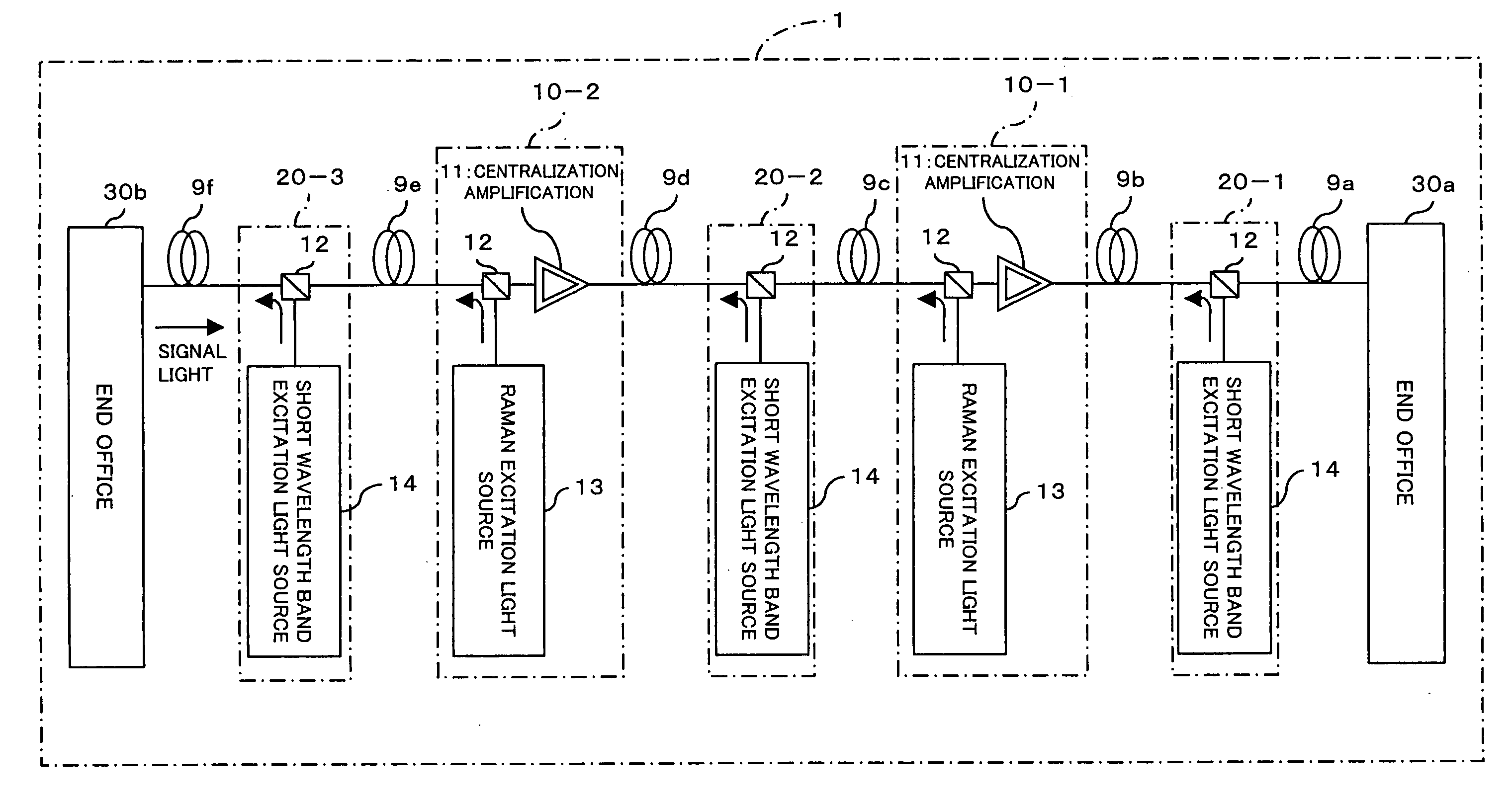
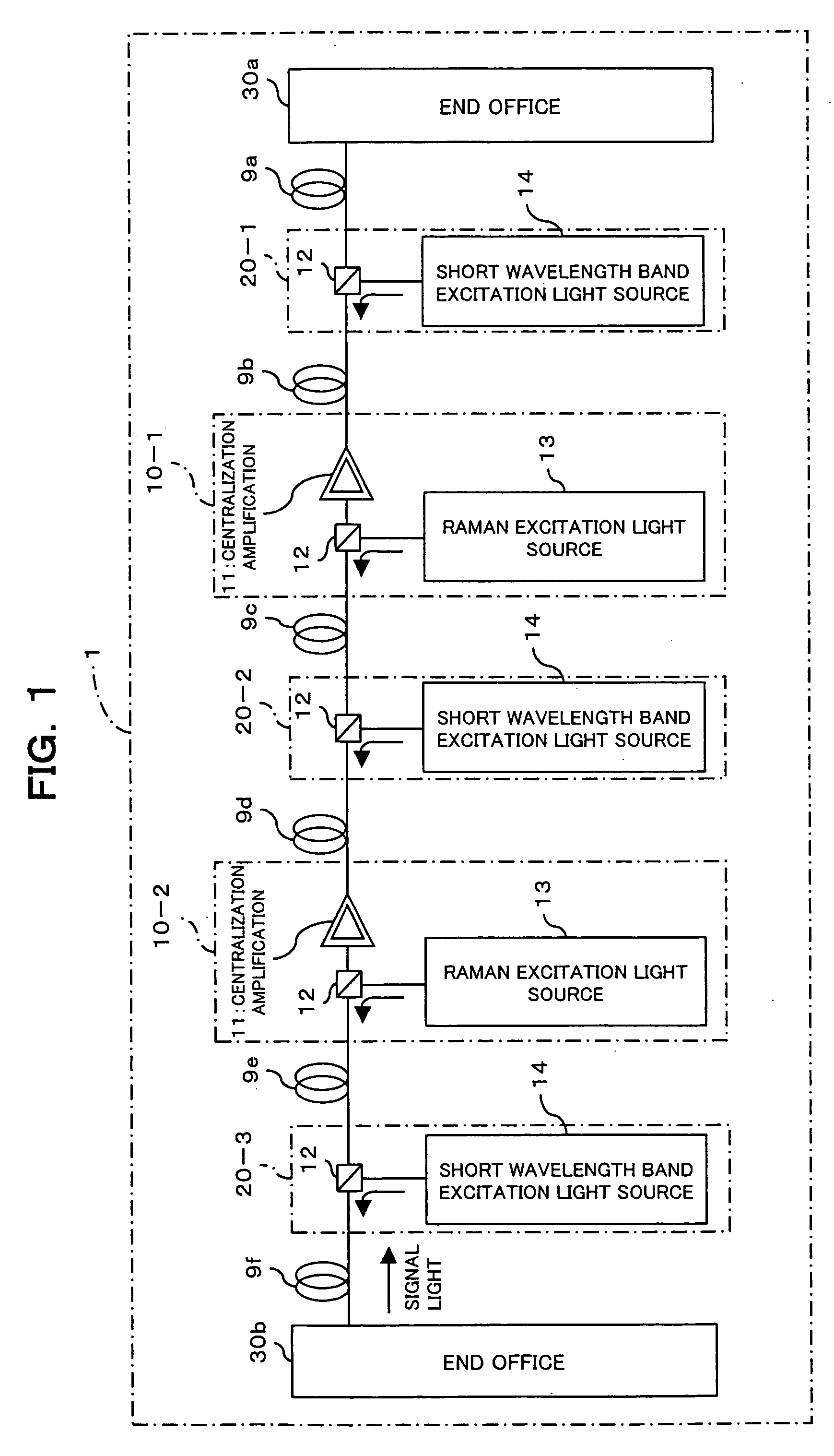
[0112]FIG. 8 shows an optical repeater system constructed according to the present invention. The optical repeater system 1a shown in the figure is constructed of optical repeaters 10a-1 and 10a-2 and optical auxiliary repeaters 20a-1, 20a-2, and 20a-3. Note in FIG. 8 that the parts with the same reference numerals as those of FIG. 1 have the same or similar function.

[0113] The optical auxiliary repeaters 20a-1, 20a-2 are equipped with short-wavelength band excitation light sources 14-1 and 14-2 for amplifying a short wavelength band component, and couplers 12-1, 12-2. A signal light and excitation light are wavelength-multiplexed at the couplers 12-1 and 12-2, whereby forward excitation and backward excitation are both performed on the signal light.

[0114] This can further reduce loss due to Stimulated Raman Scattering and loss in the short wavelength band light having a great loss due to optical fibers, and therefore can reduce the output of the excitation light that is emitted fr...


PUM

PropertyMeasurementUnit
wavelengthaaaaaaaaaa
zero-dispersion wavelengthaaaaaaaaaa

Abstract

In a WDM transmission system employing a plurality of short wavelength bands having great attenuation due to optical fiber transmission, an optical repeater is constructed of a first multiplexing section and a second multiplexing section. The first multiplexing section is used for wavelength-multiplexing both the excitation light from a first Raman excitation light source, which distributively amplifies an S+ band included in light propagating through an optical fiber, and the light propagating through the optical fiber. The second multiplexing section is used for wavelength-multiplexing both the excitation light from a second Raman excitation light source, which distributively amplifies an S+ band included in light propagating through an optical fiber, and the light propagating through the optical fiber. The first and second multiplexing sections are provided between the optical fibers disposed between end offices. Thus an equal and satisfactory optical SN ratio even at any band are obtained.

Description

BACKGROUND OF THE INVENTION [0001] (1) Field of the Invention [0002] The present invention relates to an optical transmission system, an optical repeater, and an optical transmission method suitable, for example, for a wavelength division multiplexing (WDM) system employing a short wavelength band. [0003] (2) Description of the Related Art [0004] A WDM system (optical transmission system), which employs a wavelength-multiplexed signal light consisting of a signal light having a plurality of different wavelengths, is being employed to transmit an electrical signal such as voice, data, etc. [0005] In this WDM system, one end office (or one transmission end office) optically modulates and multiplexes electrical signals output from an exchange and transmits the wavelength-multiplexed signal light to an optical repeater of the initial stage. The signal light from the optical repeater is transmitted to a plurality of optical repeaters and is demodulated by the other end office. The demodu...

Claims


Application Information

Patent Timeline
Patent Type & Authority Applications(United States)
IPC IPC(8): H01S3/00G02F1/35H01S3/06H01S3/067H01S3/10H01S3/23H01S3/30H04B10/25H04B10/2507H04B10/29H04B10/294H04B10/297H04J14/00H04J14/02
CPCH04B10/2916
Inventor NAKAMURA, KENTAROTERAHARA, TAKAFUMIHAINBERGER, RAINERKUMASAKO, JUNICHI
Owner FUJITSU LTD
Why Eureka
Try Eureka