
Motor assisted mechanical supercharging system

a supercharging system and motor technology, applied in the direction of mechanical equipment, combustion engines, machines/engines, etc., can solve the problems of low air pressure, many vehicles need maximum power during acceleration from standstill, and the supercharging speed and therefore the generation of more power, so as to reduce the parasitic drag on the engine

Inactive Publication Date: 2006-08-17
ST JAMES DAVID
View PDF18 Cites 46 Cited by
  • Summary
  • Abstract
  • Description
  • Claims
  • Application Information

AI Technical Summary

Benefits of technology

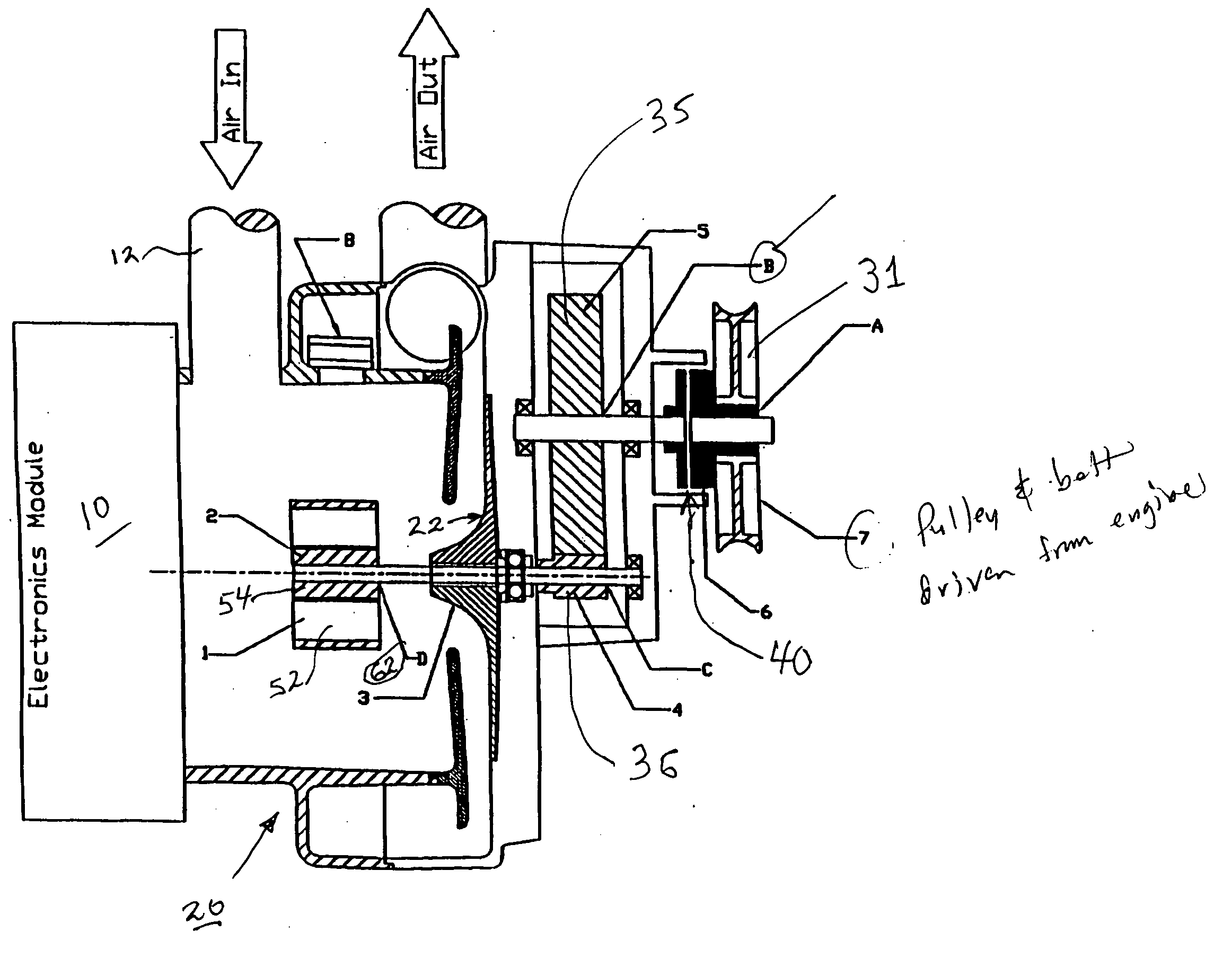
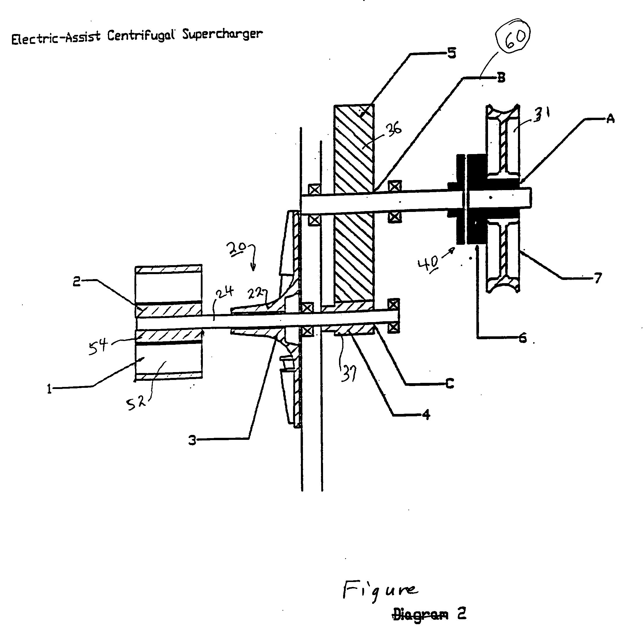
[0009] A one-way clutch and / or a magnetic clutch placed between the compressor drive shaft and the pulley for the belt drive or gear for a gear drive, will disconnect the compressor drive shaft from the engine so that the electric motor can freely accelerate the compressor to optimum speed. Once the electric motor has been switched off, the one-way clutch will engage so that engine power will drive the compressor for sustained high power operation.
[0011] Under low load conditions, the magnetic clutch can also be used to disconnect the compressor from the engine for the purpose of reducing parasitic drag on the engine, and the electric motor drive is switched off.

Problems solved by technology

Therefore, the faster the engine turns, the faster the supercharger speed and therefore higher air pressure and more power is generated.
The drawback of supercharging, however, is the fact that many vehicles need maximum power during acceleration from stand still, such as at a traffic light.
In such instances, the engine is running at low idle speed, which in turn is rotating the supercharger at a low speed, resulting in very low air pressure.
Although generation of power at high engine speeds is beneficial for high vehicle speeds and heavy load carrying applications, the lack of increased power during acceleration is a serious drawback, particularly in applications with a diesel engine when reduced air flow during acceleration results in emission of black smoke.

Method used


Image

  • Motor assisted mechanical supercharging system
  • Motor assisted mechanical supercharging system
  • Motor assisted mechanical supercharging system

Examples


Embodiment Construction

Drawing FIGS. 1-7

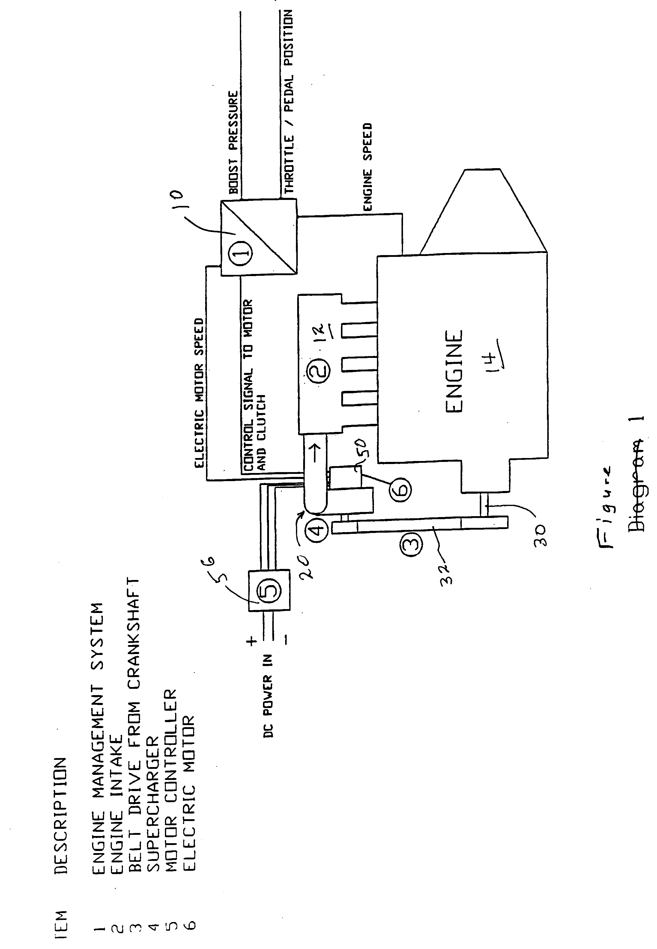
[0026] The invention is illustrated in the context of an internal combustion engine having an engine management system 10, an air intake 12 for the engine, and an engine 14. A compressor assembly 20 includes a compressor 22, supported on a compressor drive shaft 24. A by-pass valve 26 is optional for use with the compressor.

[0027] In accordance with standard engine practice, there is a rotating drive mechanism 30 which delivers rotary power from the engine output to compressor shaft 24. The rotating drive includes a pulley wheel 31 driving a belt 32. Belt 32 in turn drives a gear train 35 which includes a spur gear 36 and a pinion gear 37.

[0028] In the embodiment of FIGS. 1-7 a magnetic clutch 40 is placed at a desired location in the rotating drive mechanism 30 for the purpose of selectively turning on the compressor operation. As is well known, the magnetic clutch can be quickly activated to maintain the driving relationship of the successive portions of the dri...


PUM


Abstract

Internal combustion engine with a centrifugal compressor or positive displacement air supercharger incorporating a high speed electric motor on the drive shaft for the purpose of acceleration and generation of pressurized air at low engine speeds and incorporation of one-way and / or magnetic clutches for efficient operation.

Description

CROSS REFERENCE TO RELATED APPLICATION [0001] This application claims the priority of my Provisional application, Ser. No. 60 / 652,264, filed Feb. 14, 2005.FIELD OF INVENTION [0002] This invention relates generally to intake air charging systems for internal combustion engines. BACKGROUND OF THE INVENTION [0003] Application of superchargers in internal combustion engines, whereby pressurized air is generated by means of a centrifugal compressor or a positive displacement air pump such as a roots blower, have been in practice for many years. The power to operate the supercharger is obtained from the engine itself, by means of a belt and pulley arrangement or direct gear drive. [0004] Supercharging enables the engine to generate more power by means of a higher volume of air being fed to the engine under pressure and corresponding adjustment to fuel flow. It is not uncommon to increase engine power by 50% or higher with the aid of a supercharger, proportional to the pressure of boosted ...

Claims


Application Information

Patent Timeline
IPC IPC(8): F02B33/00
CPCF02B33/40F02B33/446F02B39/04F02B39/10F02B39/12
Inventor ST. JAMES, DAVID
Owner ST JAMES DAVID
Learn More