Solid polymer electrolyte composite membrane comprising porous ceramic support

a technology of porous ceramic support and composite membrane, which is applied in the direction of fuel cells, primary cells, secondary cells, etc., can solve the problems of premature failure of cell operation, increased shorting, and increased tensile strength of pfsa pems

Active Publication Date: 2006-08-17
PLUG POWER
View PDF24 Cites 71 Cited by
  • Summary
  • Abstract
  • Description
  • Claims
  • Application Information

AI Technical Summary

Benefits of technology

[0016] In a preferred embodiment, the ceramic support contains or is made of at least one of silica, quartz, glass, boron carbonate, silicon carbide, alumina, titania, silica tungstate, sintered valve metal oxides (e.g., tantalum or niobium oxide) and non-conductive diamond or diamond-like coatings, the support having a thickness of about 1 μm to 50 μm. A plurality of cylindrical pores are formed in the support by laser micromachining. The pores have a diameter of about 1 μm to 200 μm and are arranged in a defined pattern, such as in a uniform hexangular pattern or in a pattern in which fewer pores are located in areas of higher membrane stress and more pores are located in areas of lower membrane stress. A solid polymer electrolyte, such as PFSA polymer, fills the pores. This may be effected, for example, by filling the pores with a solution / dispersion of the solid polymer electrolyte and then drying off the solvent, by filling the pores with a precursor of the solid polymer electrolyte and then converting said precursor to said solid polymer electrolyte by base hydrolysis, or by filling the pores with a monomer of the solid polymer electrolyte and then polymerizing the monomer in-situ. Additional solid polymer electrolyte, which may be the same as or different than that filling the pores, may be applied to one or both of the top and bottom surfaces of the ceramic support.
[0017] In another preferred embodiment, a porous ceramic support is prepared by the controlled electrochemical oxidation of a sheet of the base metal. The pores of such a support may have a diameter of about 0.01 micron to 100 microns and may be arranged in a honeycomb pattern. Where the pores have a diameter less than about 0.1 micron, the pores are preferably not filled using a solution / dispersion of the solid polymer electrolyte, but rather, are preferably filled using the techniques identified above involving base hydrolysis of a precursor or by in-situ polymerization.

Problems solved by technology

For example, one common difficulty associated with PFSA PEMs is a lack of mechanical strength, resulting in a tendency for the PFSA PEMs to tear, especially when being handled (such as during assembly of an electrochemical cell) or in stressed areas where compression is applied thereto (such as in peripheral areas of PEMs sealed under pressure to other electrochemical cell components).
Such a lack of mechanical strength also often leads to electrical shorting, which results in premature failures during cell operation as the typical porous electrodes in contact with the PEM have a tendency to penetrate the softened PEM.
This problem of shorting is even greater when the membrane is made thin (e.g., less than 25 microns) in order to decrease membrane resistance.
One such shortcoming is that the dry assembly requires special moisture-free facilities, such as a “dry room.” Another such shortcoming is that the humidification process is time-consuming.
Still another such shortcoming is that the humidification process typically results in the PEM swelling in a non-uniform manner, thereby creating stress in some areas of the PEM, as well as in other components of the cell that are in contact with the PEM, and introducing irregularities in the contact pressure applied over the entire active surface area of the PEM.
(When the contact pressure is not uniform over the entire active surface area of the PEM, the performance of the electrochemical cell is adversely affected.)
Such dimensional changes cause further stress to the PEM and to the other cell components, all of which are tightly packed together.
If sufficiently great, such stress results in damage to the PEM and / or to the cell components in contact therewith.
Such cross-linking reduces the swelling of the membrane when wet which, in turn, reduces the deterioration of the mechanical strength of the membrane when wet.
Unfortunately, however, such cross-linking tends to make the membrane undesirably brittle under dry conditions.
One disadvantage that has been noted by the present inventors regarding the foregoing composite membrane is that the pores of the expanded polytetrafluoroethylene (ePTFE) sheet tend to follow a tortuous pathway between opposing surfaces of the ePTFE sheet, as opposed to following a direct or straight pathway between opposing surfaces.
Another disadvantage that has been noted by the present inventors regarding the foregoing composite membrane is that a microporous sheet of ePTFE possesses only slightly better mechanical strength than a PFSA PEM.
Still another disadvantage that has been noted by the present inventors regarding the foregoing composite membrane is that the stretching process that is used to expand the PTFE sheet to create the desired pores tends to result in a fairly uniform yet random distribution of pores throughout the sheet and cannot be tailored to control the positioning or concentration of pores in particular regions of the sheet.
This is unfortunate because certain regions of the membrane, such as the membrane active area edges / corners or the membrane contact area with the current collector, are typically subjected to greater stresses than other regions.
Consequently, pores in these regions of high stress undesirably diminish membrane strength in those regions where membrane strength is needed most.

Method used


Image

  • Solid polymer electrolyte composite membrane comprising porous ceramic support
  • Solid polymer electrolyte composite membrane comprising porous ceramic support
  • Solid polymer electrolyte composite membrane comprising porous ceramic support

Examples


example 1

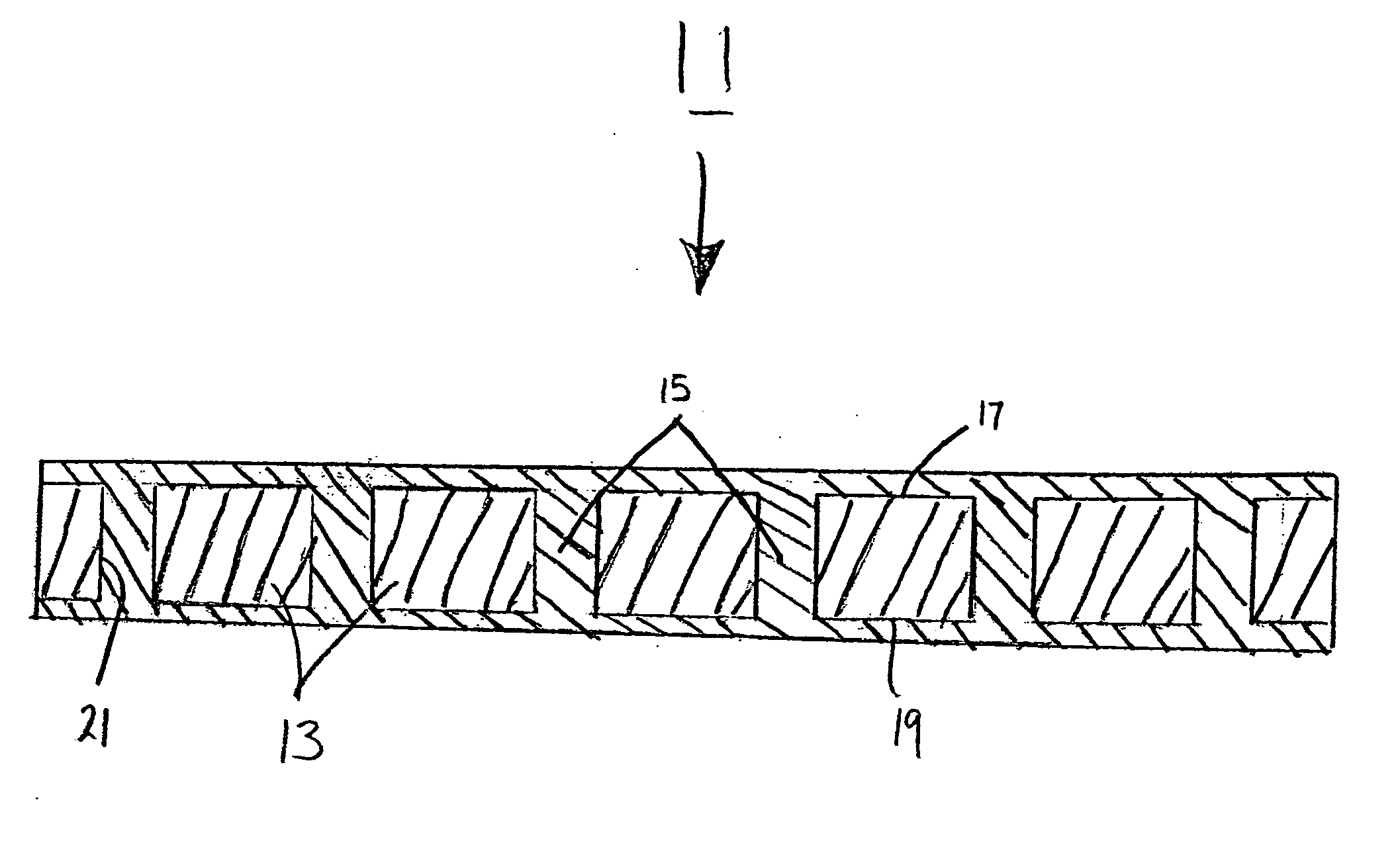
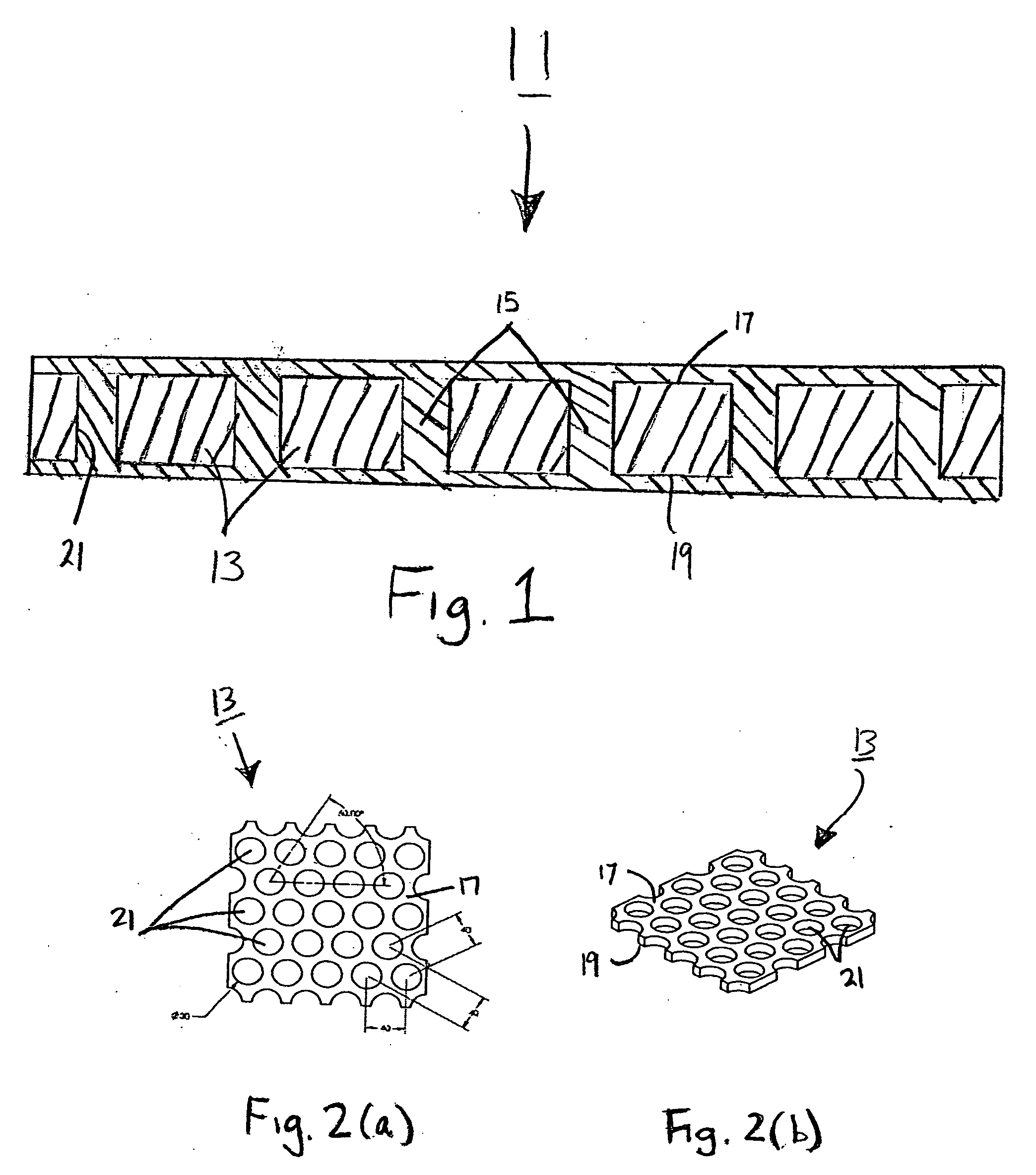
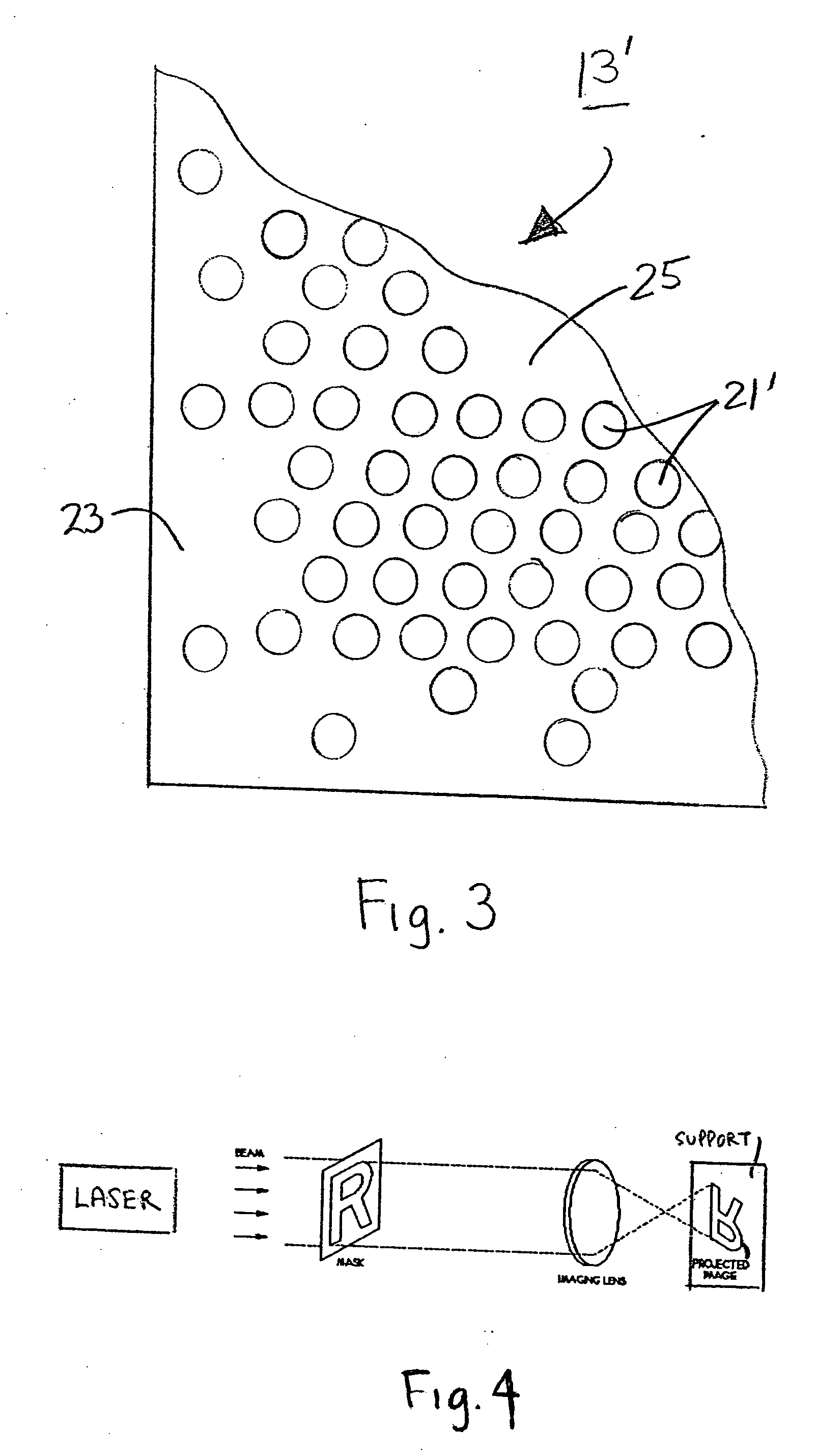
[0058] A plurality of pores were formed in a piece of 25 μm thick silica film using an excimer laser and near-field imaging. The diameter of each pore was 30 μm, and the distance between the centers of the pores was 60 μm. NAFION® PFSA solution, with an equivalent weight of 1100, was coated onto the porous film, and the product was then heated to dry off the solvent from the coated PFSA solution and to cure the PFSA polymer. The resultant composite membrane had a thickness of approximately 32 μm. The wet through-plane conductivity of the membrane was 0.05 S / cm, as compared to 0.10 S / cm for the neat ionomer.

example 2

[0059] A 25 μm NAFION® precursor membrane in the sulfonyl fluoride form was pressed into a 60 μm WHATMAN ANODISC filter having a 1.0 μm pore size. Such pressing was effected at 350° C. at 300 psi for 1 hour. Conversion of the sulfonyl fluoride form of the membrane was then effected by hydrolyzing overnight with imidazole at 60° C. The resulting wet room temperature through-plane-conductivity of the membrane was 0.04 S / cm, as compared to 0.10 S / cm for the neat ionomer.


PUM

PropertyMeasurementUnit
diameteraaaaaaaaaa
diameteraaaaaaaaaa
diameteraaaaaaaaaa

Abstract

A solid polymer electrolyte composite membrane and method of manufacturing the same. The composite membrane comprises a porous ceramic support having a top surface and a bottom surface. The porous ceramic support may be formed by laser micromachining a ceramic sheet or may be formed by electrochemically oxidizing a sheet of the base metal. A solid polymer electrolyte fills the pores of the ceramic support and preferably also covers the top and bottom surfaces of the support. Application of the solid polymer electrolyte to the porous support may take place by applying a dispersion to the support followed by a drying off of the solvent, by hot extrusion of the solid polymer electrolyte (or by hot extrusion of a precursor of the solid polymer electrolyte followed by in-situ conversion of the precursor to the solid polymer electrolyte) or by in-situ polymerization of a corresponding monomer of the solid polymer electrolyte.

Description

CROSS-REFERENCE TO RELATED APPLICATIONS [0001] The present application claims the benefit under 35 U.S.C. 119(e) of U.S. Provisional Patent Application Ser. No. 60 / 614,143, filed Sep. 29,2004, the disclosure ofwhich is incorporated herein by reference.BACKGROUND OF THE INVENTION [0002] The present invention relates generally to solid polymer electrolyte membranes of the type suitable for use in electrochemical devices and relates more particularly to a novel such membrane. [0003] Electrochemical devices ofthe type comprising a solid polymer electrolyte membrane (PEM) sandwiched between a pair of electrodes are well-known, such electrochemical devices finding applications as, for example, fuel cells, electrolyzers, sensors, gas concentrators, gas compressors, supercapacitors, ultracapacitors and industrial electrochemical process units. [0004] A common type of solid polymer electrolyte membrane consists of a homogeneous perfluorosulfonic acid (PFSA) polymer, said PFSA polymer being f...

Claims


Application Information

Patent Timeline
Patent Type & Authority Applications(United States)
IPC IPC(8): H01M8/10B05D5/12C25B1/00C08G75/24
CPCB01D69/10Y10T428/24157C25B13/08G01N27/4071H01G9/02H01G9/025H01G9/038H01G11/56H01M8/1023H01M8/1039H01M8/106H01M8/1067H01M8/1081H01M8/1083H01M8/1088H01M2300/0082H01M2300/0094Y02E60/13Y02E60/521C08J5/2218Y10T428/249954Y02P70/50Y02E60/50H01G11/84H01G11/52B01D69/108
Inventor MITTELSTEADT, CORTNEY K.LACONTI, ANTHONY B.
Owner PLUG POWER
Why Eureka
Try Eureka