
Metal-oxide based process for the generation of hydrogen from water splitting utilizing a high temperature solar aerosol flow reactor

a solar thermal reactor and aerosol flow technology, applied in the direction of manganese oxide/hydroxide, chemistry apparatus and processes, chemical/physical/physico-chemical processes, etc., can solve the problems of not releasing the world from fossil fuel dependence, and reducing the efficiency of the maximum theoretical process, so as to reduce the recombination of oxygen, and limit the heterogeneous nucleation

Inactive Publication Date: 2006-08-24
UNIV OF COLORADO THE REGENTS OF +1
View PDF20 Cites 67 Cited by
  • Summary
  • Abstract
  • Description
  • Claims
  • Application Information

AI Technical Summary

Benefits of technology

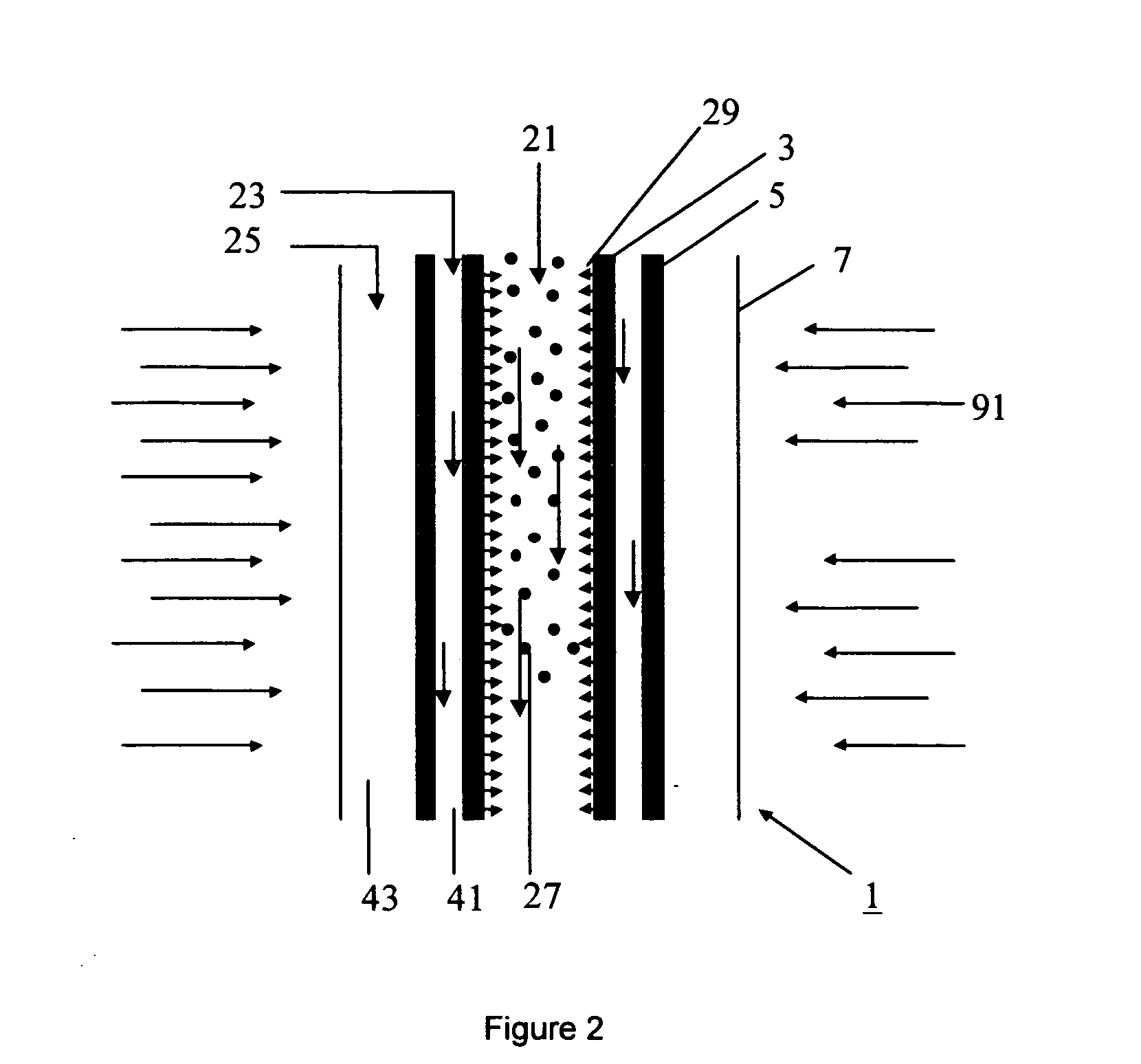
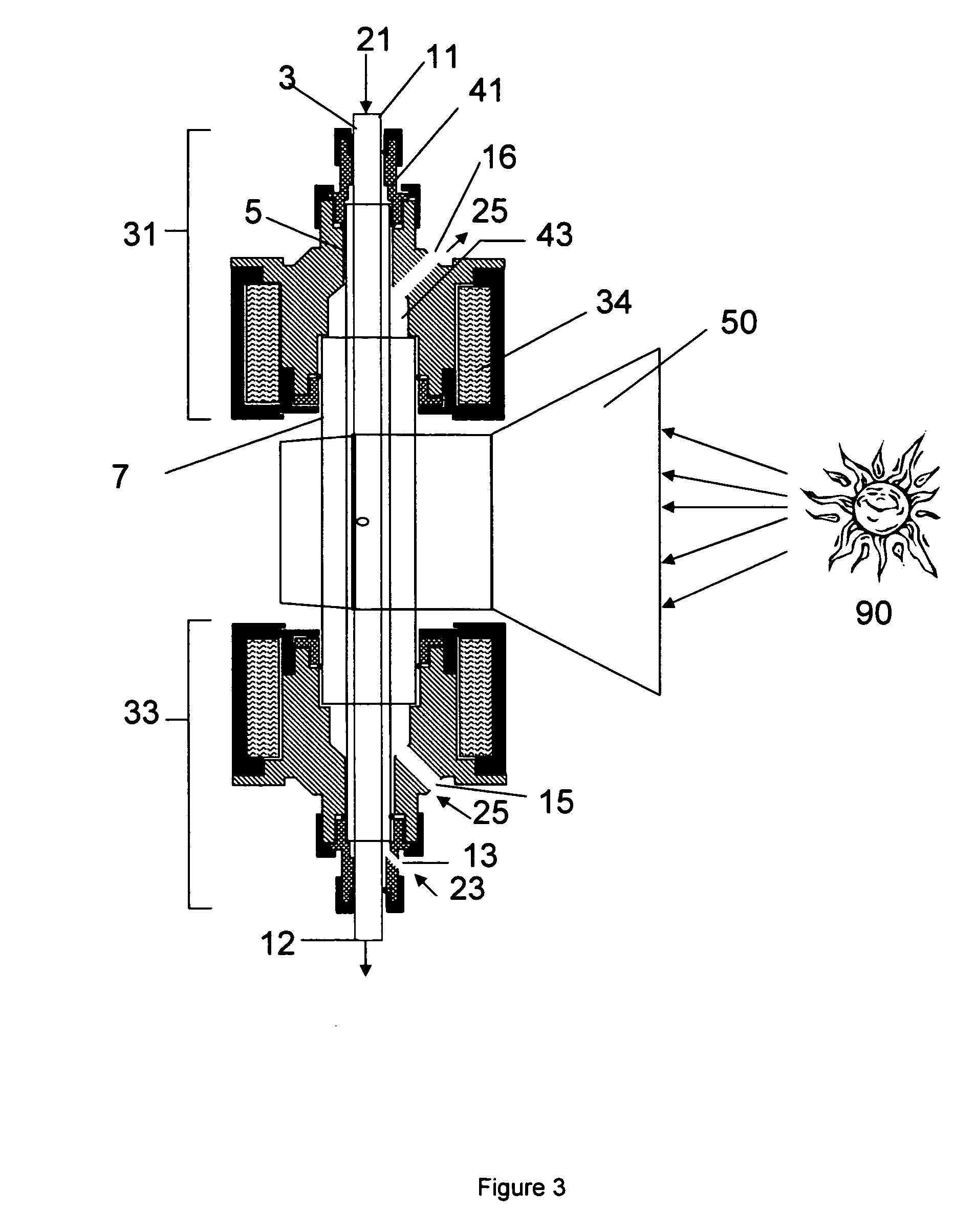
[0023] In an embodiment, the solar-thermal reactor is a fluid-wall reactor in which the reaction shell has a porous section. In an embodiment, the porous section is located at the downstream end of the reaction shell or tube. When the fluid-wall reactor is operated, a fluid-wall gas flows radially inward into the reaction shell through the porous section of the reaction shell and provides a fluid-wall on the inside of the reaction shell. The fluid wall can prevent oxidation of graphite reactor materials with the product oxygen from the metal oxide reduction. Without wishing to be bound by any particular theory, it is also believed that the fluid wall can limit heterogeneous nucleation of oxide particles on the reaction shell wall, thereby reducing recombination of oxygen with the reduced metal oxide product and increasing the yield of the reduction reaction.

Problems solved by technology

Clearly, choosing this route for the hydrogen economy does not release the world from fossil fuel dependence.
First and foremost is that as the number of process steps increases, the maximum theoretical process efficiency decreases due to the entropic irreversibility of each stage and of the material and energy transfer between stages.
With decreased efficiency comes poorer theoretical economics, overall conversion concerns, and bottom line reductions in overall energy production.
A final disadvantage of multi-step water splitting cycles is that they involve chemical reactants other than water.

Method used


Image

  • Metal-oxide based process for the generation of hydrogen from water splitting utilizing a high temperature solar aerosol flow reactor
  • Metal-oxide based process for the generation of hydrogen from water splitting utilizing a high temperature solar aerosol flow reactor
  • Metal-oxide based process for the generation of hydrogen from water splitting utilizing a high temperature solar aerosol flow reactor

Examples


example 1

Simulations of the ZnO / Zn Cycle

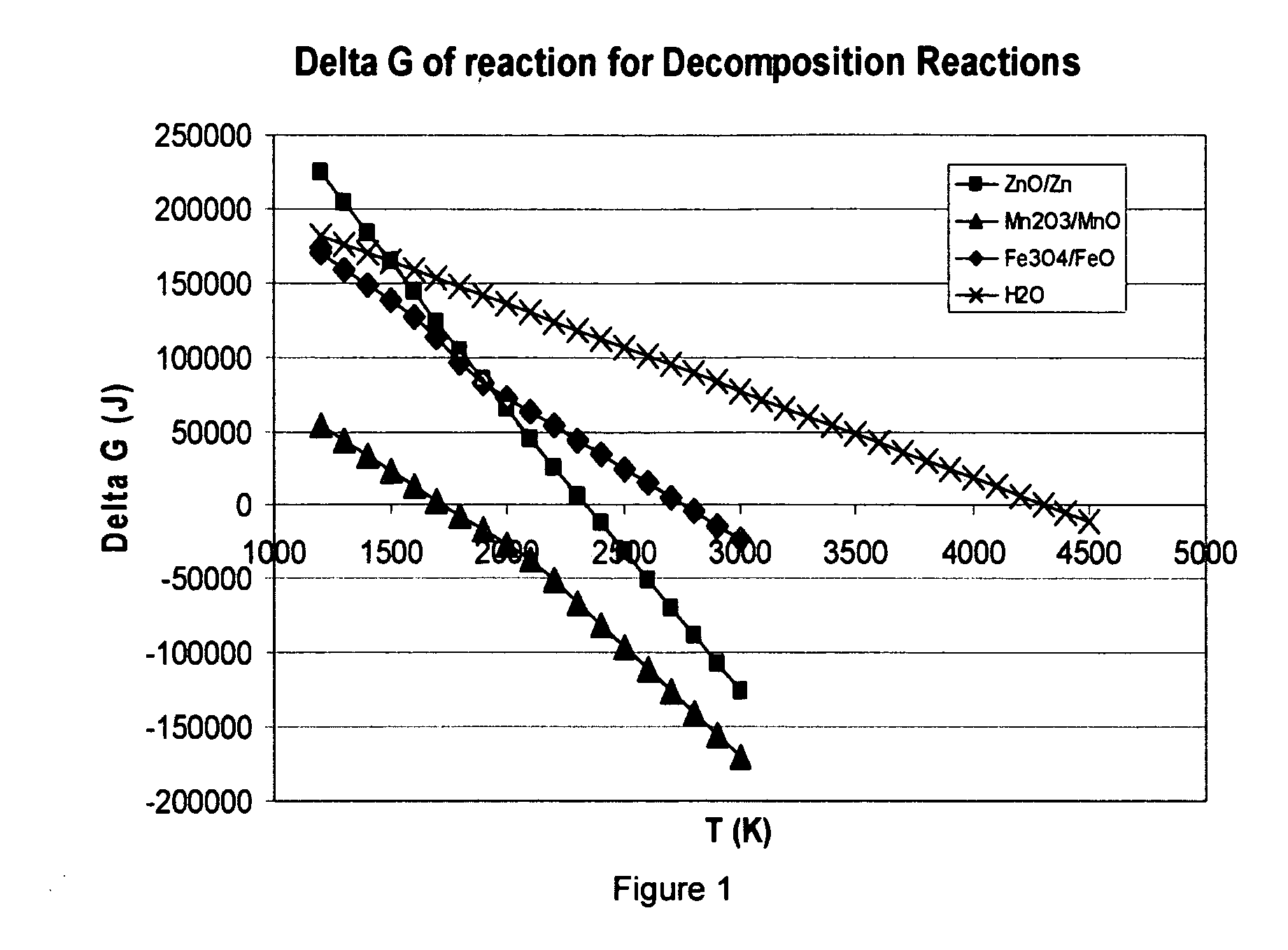
[0123] The metal-oxide cycle that has been most researched in the technical literature is the ZnO / Zn cycle. As can be seen from FIG. 1, it has a ΔGf of zero at 2255 K, making it feasible for modern solar reactor systems [11]. If the Zn is fully recovered in the decomposition step, and ZnO fully recovered in the water splitting step, it is possible to make the only reaction input H2O and the only products O2 and H2, thus completing a renewable, sustainable cycle.

[0124] The ZnO decomposition reaction was simulated using the computer program FACT, and the equilibrium composition results of this simulation are shown in FIG. 9. As can be seen, FACT predicts the start of Zn vapor formation around 1800 K, with complete conversion occurring around 2150 K. At this point, only Zn, O2, and some elemental oxygen are formed. Due to the unstable nature of elemental oxygen, this will most likely form the diatomic gas when temperatures are reduced in the post-reacti...

example 2

Simulations of the Mn2O3 / MnO Cycle

[0126] Thermodynamic simulation of the decomposition step of this reaction (Eq. (6)) was conducted using the FACT software. The equilibrium composition results of this simulation can be seen in FIG. 11. From these equilibrium data, a few interesting and desirable qualities of this system come to light. First, complete decomposition to solid phase MnO and gaseous O2 occurs around 1800 K with an equimolar inert feed. This is at a lower temperature than required for the ZnO system, allowing for higher reactor efficiency due to lower reradiation losses. In addition, the separation of gaseous O2 from solid MnO upon cooling is straightforward.

[0127] Additional calculations also show that Mn2O3 reduction is feasible in an air atmosphere.

example 3

Demonstration of Production of Zn from ZnO at Moderate Residence Times in a Conventional Aerosol Flow Reactor

[0128] To demonstrate the efficacy of ZnO dissociation in high temperature aerosol flow, ZnO oxide (size approximately 900 nm-1 μm) particles were entrained in Argon gas and fed into a conventional aerosol flow reactor without a fluid wall. Conversions exceeding 20% were observed at moderate temperatures (1600° C.) and residence times (1.0 s). At higher temperatures, faster rates of Zn production were observed.

[0129] The product Zn particles had sizes ranging from 20 nm-400 nm. These small particles would likely be more reactive with water due to decreased mass and heat transfer limitations. The particles were collected on an HEPA filter and in a gravity collection vessel, and were well dispersed and non-agglomerated. The production of this Zn powder effectively demonstrates the concept of using an aerosol reactor for ZnO dissociation.

[0130] The cooling chamber consisted o...


PUM

PropertyMeasurementUnit
Temperatureaaaaaaaaaa
Lengthaaaaaaaaaa
Melting pointaaaaaaaaaa

Abstract

The invention provides methods for reduction of metal oxide particles using a high temperature solar aerosol reactor. The invention also provides metal-oxide based processes for the generation of hydrogen from water splitting using a high temperature solar aerosol reactor. In addition, the invention provides solar thermal reactor systems suitable for use with these processes.

Description

CROSS-REFERENCE TO RELATED APPLICATIONS [0001] This application claims the benefit of U.S. Provisional Application No. 60 / 628,641, filed Nov. 17, 2004, and is a continuation-in-part of U.S. application Ser. No. 10 / 383,875, filed Mar. 7, 2003, which claims the benefit of U.S. Provisional Application No. 60 / 362,563, filed Mar. 7, 2002, and is a continuation-in-part of U.S. application Ser. No. 10 / 239,706, filed Feb. 24, 2003, which is the national stage of PCT Application Number PCT / US01 / 15160, filed May 8, 2001, which claims the benefit of U.S. Provisional Application No. 60 / 203,186, filed May 8, 2000, all of which are hereby incorporated by reference to the extent not inconsistent with the disclosure herein.ACKNOWLEDGEMENT OF GOVERNMENT SUPPORT [0002] This invention was made, at least in part, with support from the Department of Energy under grant numbers DE-FG36-03G013062 and DE-FC36-99G010454. The United States government may have certain rights in this invention.BACKGROUND OF THE...

Claims


Application Information

Patent Timeline
IPC IPC(8): C01G9/02
CPCB01J8/12B01J12/007B01J19/127B01J2219/00085B01J2219/00094B01J2219/0869B01J2219/0871B01J2219/0883B01J2219/0886B01J2219/0892C01B3/06C01B3/063C01B3/105C22B5/02C22B5/14Y02E60/36
Inventor WEIMER, ALAN W.PERKINS, CHRISTOPHERLEWANDOWSKI, ALLAN A.BINGHAM, CARL
Owner UNIV OF COLORADO THE REGENTS OF
Learn More