Optical multilayer disk, multiwavelength light source, and optical system using them

a multi-layer disk and optical technology, applied in the field of optical information recording mediums, can solve the problems of reducing light absorption aa and ac, difficulty in recording in the first recording medium, and lack of recording power with respect to the second recording medium, and achieve the effect of increasing the recording density considerably

Inactive Publication Date: 2006-08-31
PANASONIC CORP
View PDF20 Cites 14 Cited by
  • Summary
  • Abstract
  • Description
  • Claims
  • Application Information

AI Technical Summary

Benefits of technology

[0027] According to this optical information recording medium, a sufficiently high light absorptance ratio of the first recording layer and light transmittance of the first recording medium can be obtained. Therefore, by using the combination of the wavelengths λ1 and λ2, for example, the light absorptance ratio can be varied from about 1.0 to about 1.6 and the light transmittance from over 30% to over 60%. Thus, the optical information recording medium has the following effects. That is, the light absorptance ratio of the first recording layer and the light transmittance of the first recording medium are adjusted according to the materials and recording conditions of the first and second recording layers, thus obtaining excellent recording and reproduction characteristics in both the first and second recording media.
[0083] According to this configuration, recording is performed while record information is detected in real time in recording and this information is fed back to control the intensity of recording beams and the focal point on the recording medium. Consequently, shapes of recording pits to be formed in the recording medium can be controlled precisely, thus increasing recording density considerably.

Problems solved by technology

On the other hand, when the light transmittances Tc and Ta are too high, in view of the distribution of an incident beam, the light absorptances Aa and Ac decrease, thus causing difficulty in recording in the first recording medium.
In this case, the first recording medium has an insufficient erase rate, or sufficient laser beams do not reach the second recording medium, thus causing a lack of recording power with respect to the second recording medium.
As a disadvantage of the QPM-SHG element, there is a problem that the tolerance with respect to phase matching wavelengths is extremely narrow.
However, since emission parts of optical waveguides are formed at different positions, when two emission beams are intended to be focused simultaneously with one optical system, great aberration is caused and a complicated optical system is provided for obtaining focusing characteristics within the diffraction limit, which have been problems.

Method used


Image

  • Optical multilayer disk, multiwavelength light source, and optical system using them
  • Optical multilayer disk, multiwavelength light source, and optical system using them
  • Optical multilayer disk, multiwavelength light source, and optical system using them

Examples


first embodiment

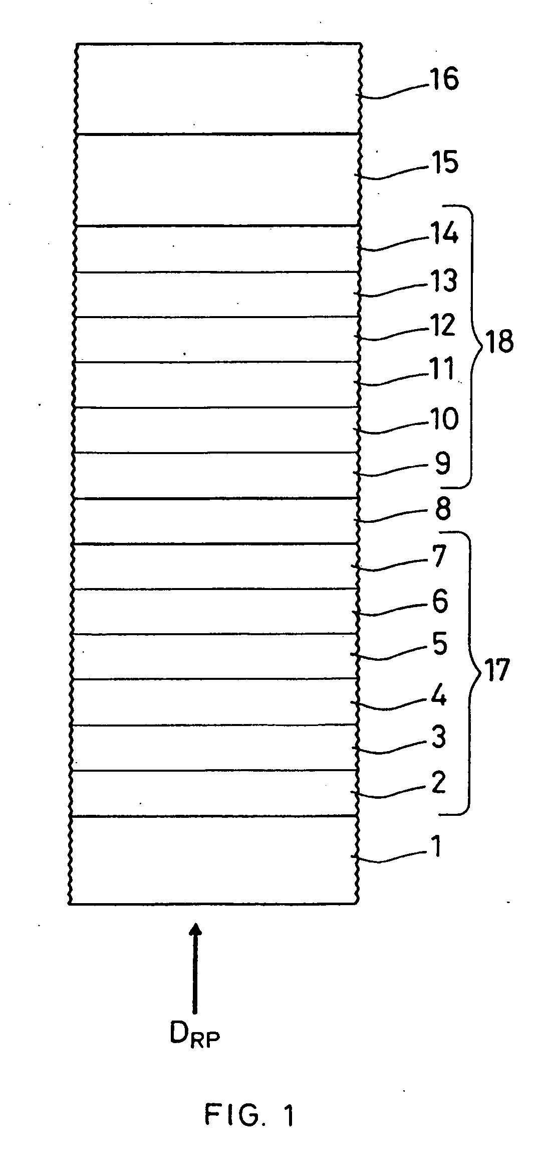
[0101]FIG. 1 shows a structural example of an optical information recording medium according to a first embodiment of the present invention. This optical information recording medium has the following configuration. On a substrate 1, a first lower optical interference layer 2, a first lower interface layer 3, a first recording layer 4, a first upper interface layer 5, a first upper optical interference layer 6, and a first reflective layer 7 are stacked sequentially. Subsequently, a separation layer 8 is provided on the first reflective layer 7. On the separation layer 8, a second lower optical interference layer 9, a second lower interface layer 10, a second recording layer 11, a second upper interface layer 12, a second upper optical interference layer 13, and a second reflective layer 14 are stacked sequentially. This stacked body is bonded to a dummy substrate 16 with an adhesion layer 15, thus forming the optical information recording medium. The multilayer structure from the f...

second embodiment

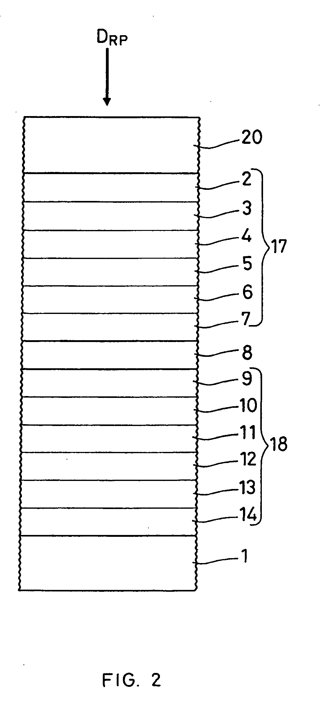
[0118]FIG. 2 shows a structural example of an optical information recording medium according to a second embodiment of the present invention. This optical information recording medium has the following configuration. On a substrate 1, a second reflective layer 14, a second upper optical interference layer 13, a second upper interface layer 12, a second recording layer 11, a second lower interface layer 10, and a second lower optical interference layer 9 are stacked sequentially. Subsequently, a separation layer 8 is provided on the second lower optical interference layer 9. On the separation layer 8, a first reflective layer 7, a first upper optical interference layer 6, a first upper interface layer 5, a first recording layer 4, a first lower interface layer 3, and a first lower optical interference layer 2 are stacked sequentially. On the first lower optical interference layer 2, a protective layer 20 is provided. The multilayer structure from the first lower optical interference ...

third embodiment

[0123]FIG. 3 shows a structural example of an optical information recording medium according to a third embodiment of the present invention. This optical information recording medium has the following configuration. On a substrate 21, a first lower optical interference layer 2, a first lower interface layer 3, a first recording layer 4, a first upper interface layer 5, a first upper optical interference layer 6, and a first reflective layer 7 are stacked sequentially. On a second substrate 22, a second reflective layer 14, a second upper optical interference layer 13, a second upper interface layer 12, a second recording layer 11, a second lower interface layer 10, and a second lower optical interference layer 9 are stacked sequentially. The multilayer structure from the first lower optical interference layer 2 to the first reflective layer 7 is a first recording medium 17. Similarly, the multilayer structure from the second lower optical interference layer 9 to the second reflectiv...


PUM

PropertyMeasurementUnit
angleaaaaaaaaaa
wavelengthsaaaaaaaaaa

Abstract

When a wavelength of a first laser beam with which a first recording medium including a first recording layer is recorded and reproduced is indicated as λ1 (nm), a wavelength of a second laser beam with which a second recording medium including a second recording layer is recorded and reproduced as λ2 (nm), the relationship between the wavelength λ1 and the wavelength λ2 is set to be expressed by 10≦|λ1−λ2|≦120. The first recording layer has a light absorptance ratio of at least 1.0 with respect to the wavelength λ1. The light transmittance of the first recording medium with respect to the wavelength λ2 is set to be at least 30 in both the cases where the recording layer is in a crystal state and in an amorphous state. In order to record and reproduce the optical multilayer disk with the above-mentioned characteristics, a multiwavelength light source with the following configuration is used. Wavelengths of fundamental waves with different wavelengths from injection parts formed at one end of a plurality of optical waveguides, which satisfy phase matching conditions different from one another and are formed in the vicinity of the surface of a substrate, are converted simultaneously, and the first and second laser beams are emitted from emission parts formed at substantially the same position at the other end of the optical waveguides. This enables an optimum optical system for high density recording and reproduction to be obtained.

Description

[0001] The application is a divisional of U.S. application Ser. No. 09 / 694,625, filed Oct. 23, 2000, which application is incorporated herein by reference.BACKGROUND OF THE INVENTION [0002] 1. Field of the Invention [0003] The present invention relates generally to an optical information recording medium in which information is recorded and reproduced optically with respect to recording layers in a multilayer, i.e. an optical multilayer disk, and to a method of recording and reproducing with respect to the same. The present invention also relates generally to an optical waveguide device, to which a coherent light source is applied, used in fields of optical information processing and optical application instrumentation and further to a multiwavelength light source using such an optical waveguide device and an optical system using such a multiwavelength light source for recording and reproduction of information with respect to the optical multilayer disk. [0004] 2. Related Background...

Claims


Application Information

Patent Timeline
Patent Type & Authority Applications(United States)
IPC IPC(8): G11B7/135G02B6/10G11B7/26G02B6/12G02B6/126G02B6/34G02F1/35G02F1/377G11B7/00G11B7/0045G11B7/005G11B7/12G11B7/125G11B7/24G11B7/24038G11B7/243G11B7/258G11B7/259
CPCG02B6/126G02B6/29362G02B2006/12164G02F1/3532G02F1/3544G02F1/3775G02F2001/3548G02F2201/18G02F2203/58G11B7/00454G11B7/005G11B7/1206G11B7/1275G11B7/1395G11B7/24038G11B7/243G11B7/259G11B7/26G11B2007/0013G11B2007/24312G11B2007/24314G11B2007/24316G11B7/124G02F1/3548
Inventor MIZUUCHI, KIMINORIYAMAMOTO, KAZUHISAKOJIMA, RIEYAMADA, NOBORU
Owner PANASONIC CORP
Why Eureka
Try Eureka