Eureka AIR delivers breakthrough ideas for toughest innovation challenges, trusted by R&D personnel around the world.

Optical switches and routers and optical filters

Inactive Publication Date: 2006-08-31
ARRYX INC
View PDF8 Cites 28 Cited by
  • Summary
  • Abstract
  • Description
  • Claims
  • Application Information

AI Technical Summary

Benefits of technology

[0033] Adjustment of the proximity of the microsphere to the stripped or thinly clad region of the optical fibers may provide a controllable index of refraction of “n±x” for the microsphere, wherein as “x” approaches zero, the efficiency of the transfer of signal approaches the microsphere's maximum obtainable coupling efficiency which may be useful for applications such as channel equalizing, grooming and power balancing.
[0055] The mechanisms for adjusting the nrs is the same type of linear electro optic effects and / or optical effects used in the first WGM control. However, the adjustment in the nrs is to effectively blend the resonate structure into the medium.
[0058] Mechanisms for adjusting nrs(gate keeper) or nrs(isolator) include polarization of the resonant structure by an applied voltage or current causing a linear electro-optic effect or by an applied beam of light causing an optical effect.
[0059] The fourth WGM control is used to switch “on / off” the optical filter based on an adjustment of nrs(gate keeper) or nrs(isolator) relative to the index of refraction of a medium “nmedium” surrounding at least one resonate structure waveguide interface, to establish conditions which either interrupt or encourage signal coupling between the subfilters and the input and / or the output waveguide(s). The mechanisms for adjusting the nrs is the same type of linear electro optic effects and / or optical effects used in the first WGM control. However, the adjustment in the nrs is to effectively blend the resonate structure into the medium. “On / Off” Switching Control Through Signal Loss

Problems solved by technology

The speed of routing from one optical fiber to another is limited by the rate at which the optical switching occurs.
In the past, switches which convert the optical data to electronic data have been a “bottleneck” in the system.
This may yield turbidity within a band resulting in unbalanced light transmissions (signals) from channel to channel which in turn may cause noise, loss of part of a signal or channels to drop out.

Method used


Image

  • Optical switches and routers and optical filters
  • Optical switches and routers and optical filters
  • Optical switches and routers and optical filters

Examples


Embodiment Construction

[0097] Certain terminology will be used in the following specification for convenience and reference, and not as a limitation. Brief definitions are provided below:

[0098] A. An “evanescent wave” refers to a wave that occurs when a wave enters a region in which it cannot propagate. Typically such waves are characterized by an amplitude which decreases exponentially with distance into the region in which the wave cannot propagate.

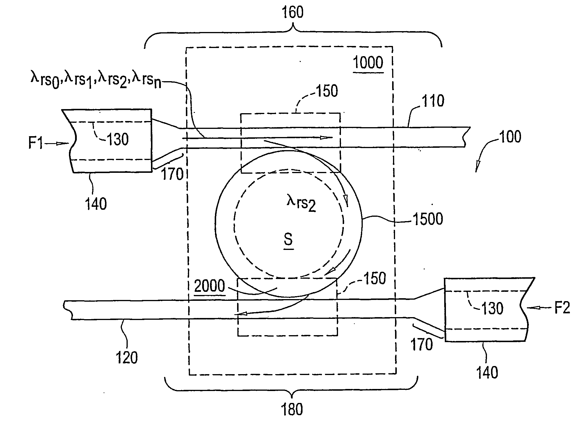
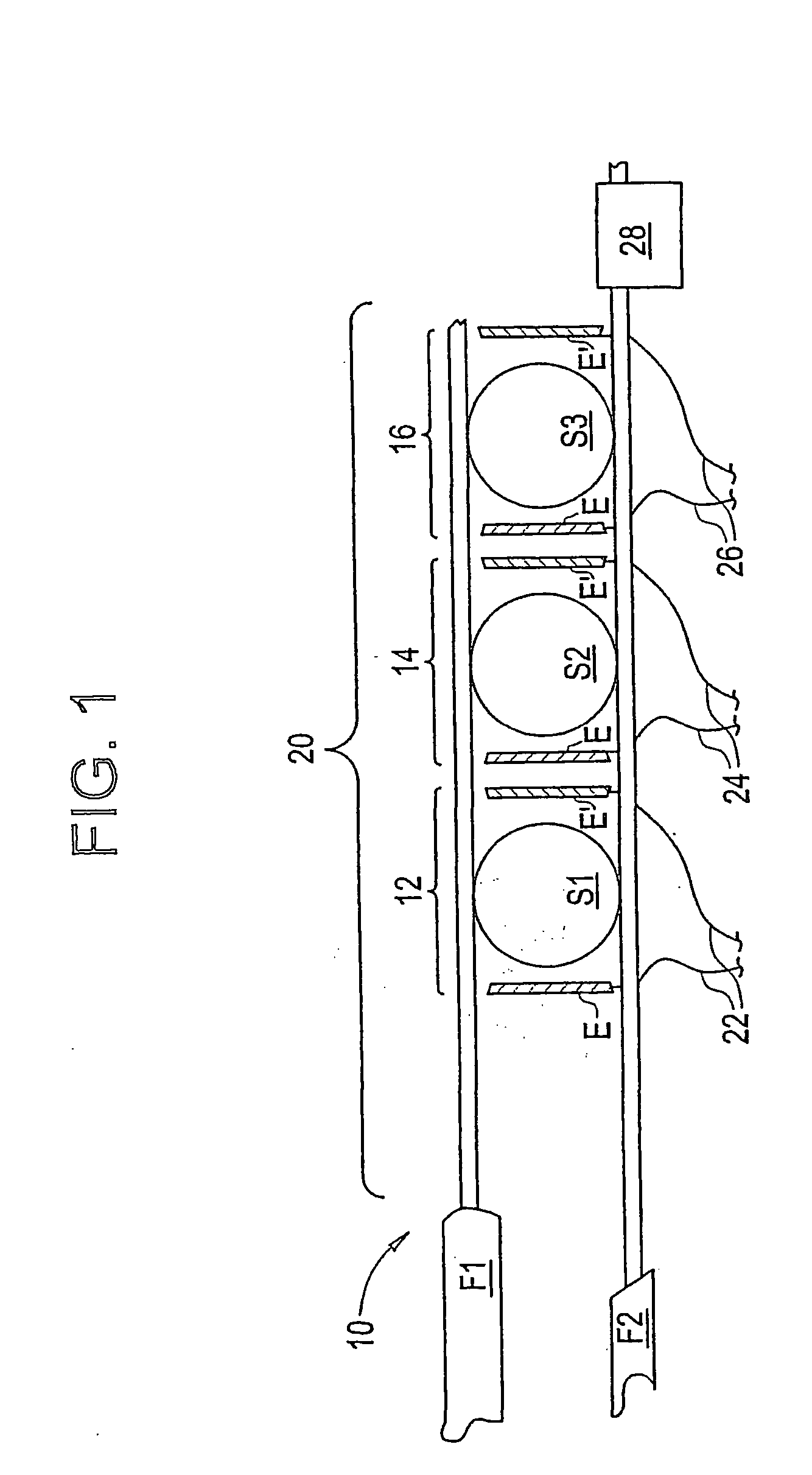
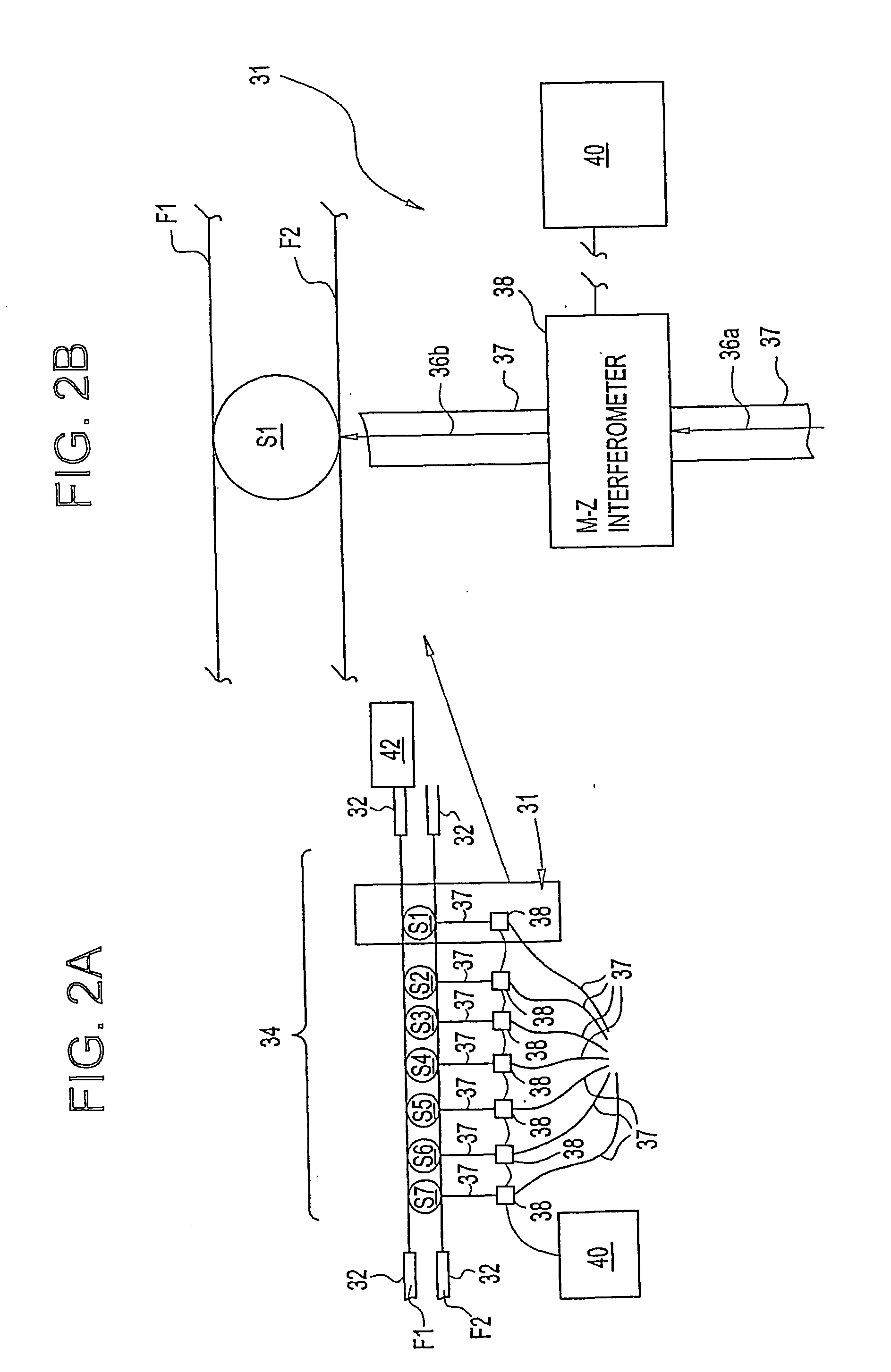
[0099] B. “WGM” refers to the whispering gallery mode, which is a property of resonate structures that can be used to form a wavelength specific optical conduit between one or more optical fibers and the resonate structure via evanescent waves.

[0100] C. “Beamlet” refers to a sub-beam of light or other source of energy that is generated by directing a light or other source of energy, such as that produced by a laser or collimated output from a light emitting diode, through a medium which diffracts it into two or more sub-beams. An example of a beamlet would...


PUM


Abstract

Our invention relates generally to an optical switch (31) and an optical router (10) to rapidly route signals from particular channels (22, 24) within an optical band by using optical switches (20) which utilize a controlled whispering gallery mode (WGM) resonance of dielectric microspheres (S1, S2, S3) to optically switch signals. Another invention relates to optical filters which use a WGM resonate structure (150) to isolate and switch specific optical signals between waveguides (F1, F2). In other inventions, the filter (100) is switched “on / off” by signal loss within a WGM resonate structure (150) which disrupts the WGM resonance; the filter (100) isolates and switches a specific wavelength signal from among a group of signals of different wavelengths; and is switched “off” by adjusting the index of refraction of the resonate structure to become substantially similar to the index of refraction of the surrounding medium.

Description

[0001] This is a PCT Application which claims priority to U.S. application Ser. No. 09 / 886,698, filed Jun. 20, 2001, U.S. application Ser. No. 10 / 118,532, filed Apr. 8, 2002, U.S. application Ser. No. 10 / 118,531, filed Apr. 8, 2002, U.S. application Ser. No. 10 / 118,709, filed Apr. 8, 2002, and U.S. application Ser. No. 10 / 118,760, filed Apr. 8, 2002, the entire contents of which are herein incorporated by reference.BACKGROUND OF THE INVENTION [0002] Throughout this application various publications are noted. The disclosures of these publications in their entireties are hereby incorporated by reference in this application in order to more fully describe the state of the art to which this invention pertains. [0003] 1. Field of the Invention [0004] The present application discloses one or more inventions. The inventions relate generally to optical switching, and in particular, one invention relates to methods, devices and systems to optically switch a specific channel of light between ...

Claims


Application Information

Patent Timeline
IPC IPC(8): G02B6/26G02B6/42G02B6/34G02F1/313
CPCG02B6/12007G02B6/29341G02B6/29343G02F1/3132G02F2203/15
Inventor BRADLEY, KENNETHLOPES, WARD
Owner ARRYX INC
Why Eureka
Eureka Blog
Learn More