Thermal interface material and filler used therein

a technology of thermal interface material and filler, which is applied in the direction of cellulosic plastic layered products, natural mineral layered products, transportation and packaging, etc., can solve the problems insufficient conductivity of metal-oxide ceramics, and inability to meet the requirements of thermal dissipation performance, etc., to achieve high dielectric strength, reduce the electric conductivity of filler, and reduce the effect of short circuit between devices

Inactive Publication Date: 2006-09-07
COMPAL ELECTRONICS INC
View PDF1 Cites 6 Cited by
  • Summary
  • Abstract
  • Description
  • Claims
  • Application Information

AI Technical Summary

Benefits of technology

[0018] By forming a non-electrically conductive or low-electrically conductive film on the surface of each electrically conductive particle, the electrical conductivity of the filler is reduced. Under thermal

Problems solved by technology

However, the metal powder is more electrically conductive, and after a period of time, the metal powder may cause short circuits between devices due to deterioration of materials o

Method used


Image

  • Thermal interface material and filler used therein
  • Thermal interface material and filler used therein

Examples


Embodiment Construction

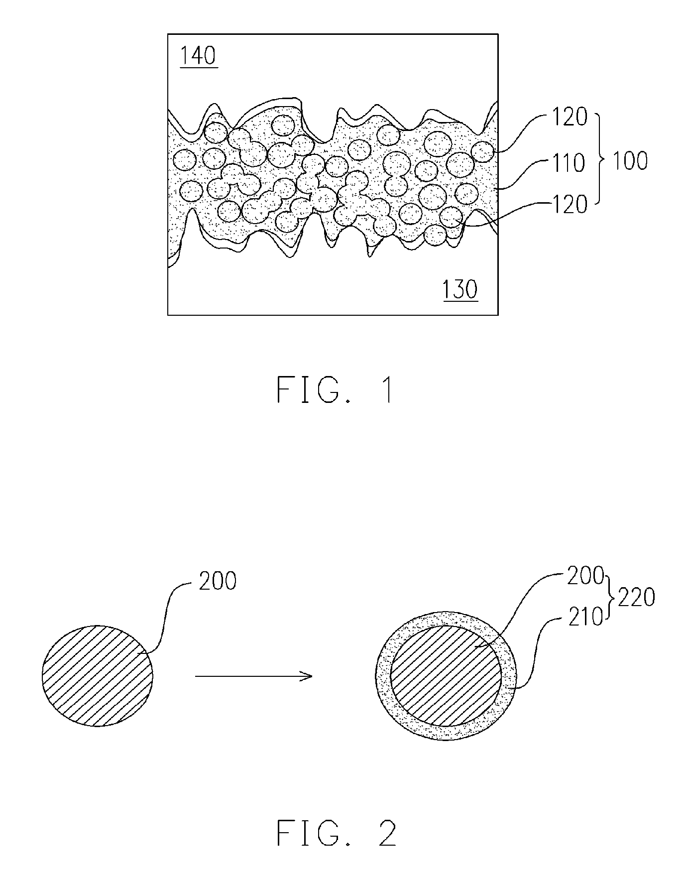
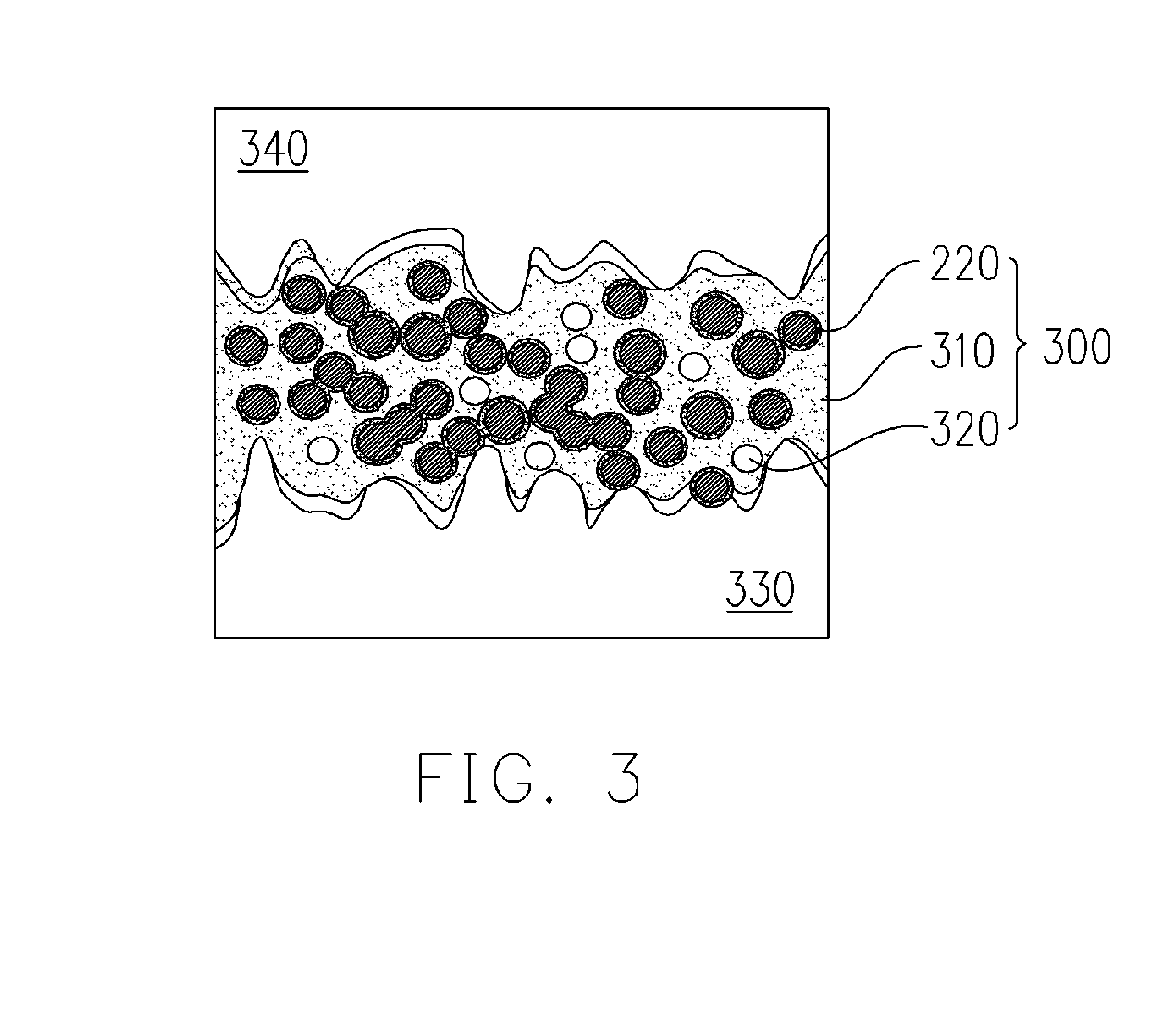
[0023] In the thermal interface material (TIM) of the present invention, electrically conductive particles with high thermal conductivity are preferred. Preferably, the material of the electrically conductive particles in the TIMs of the present invention is noble metal, base metal or electrically conductive polymer. More preferably, the material of the electrically conductive particles is gold, silver or copper. Preferably, the material of the non-electrically conductive film in the TIMs of the present invention is metal oxide, nitride, low-electrically conductive graphite in various types, diamond, low-electrically conductive organic polymer, carbide or metal ceramics. In the TIMs of the present invention, the non-electrically conductive film on the surface of the electrically conductive particle can be formed by any conventional film-forming processes, among which chemical vapor deposition (CVD), physical vapor deposition (PVD), micro-capsule deposition or oxidation are preferred...


PUM

PropertyMeasurementUnit
Fractionaaaaaaaaaa
Thicknessaaaaaaaaaa
Electrical conductivityaaaaaaaaaa

Abstract

A filler used in thermal interface materials (TIMs) is disclosed. The filler is composed of a plurality of electrically conductive particles, on which a non-electrically conductive films is formed for preventing the electrically conductive particles from electrical conducting with each other. The present invention also provides a thermal interface material (TIM) including the above-mentioned filler.

Description

CROSS-REFERENCE TO RELATED APPLICATION [0001] This application claims the priority benefit of Taiwan application serial no. 94106403, filed on Mar. 3, 2005. All disclosure of the Taiwan application is incorporated herein by reference. BACKGROUND OF THE INVENTION [0002] 1. Field of Invention [0003] The present invention relates to a thermal interface material (TIM) and, more particularly, to a filler used in the thermal interface material. [0004] 2. Description of the Related Art [0005] In recent technology, the processing speed and the operation efficiency of a central processing unit (CPU) is substantially enhanced. The major breakthrough is that the linewidth of a CPU chip has reached a 90 nanometer. Along with an increased clock frequency, smaller transistors and a denser chip layout, the number of transistors disposed on a same area has doubled, which results in nearly double heat generation in a same chip area. To facilitate the heat dissipation, normally a cooling component is...

Claims


Application Information

Patent Timeline
IPC IPC(8): C08K9/00B32B5/16
CPCH01L23/3733H01L2924/0002Y10T428/2991H01L2924/00
Inventor FAN, KUANG-CHENGDENQ, BAR-LONGKUO, FANG-LING
Owner COMPAL ELECTRONICS INC
Why Eureka
Try Eureka