
Methods of maximizing retention of superabrasive particles in a metal matrix

Inactive Publication Date: 2006-09-28
SUNG CHIEN MIN
View PDF5 Cites 52 Cited by
  • Summary
  • Abstract
  • Description
  • Claims
  • Application Information

AI Technical Summary

Benefits of technology

[0013] Various mechanisms of moderating chemical bonding between the superabrasive particles and the metal matrix are contemplated, all of which are intended to be included within the scope of the present invention. Such moderation may include varying the available amount of a reactive element in the metal matrix. In one aspect, for example, moderating chemical bonding may include moderating or even minimizing the relative amount of a reactive element in the metal matrix.

Problems solved by technology

A problem with maintaining the top of the pad is caused by an accumulation of polishing debris coming from the work piece, abrasive slurry, and dressing disk.
This accumulation causes a “glazing” or hardening of the top of the pad, and mats the fibers down, thus making the pad less able to hold the abrasive particles of the slurry, and thus significantly decreases the pad's overall polishing performance.
Further, with many pads the pores used to hold the slurry become clogged, and the overall asperity of the pad's polishing surface becomes depressed and matted.
However, because the matrix surrounding the superabrasive particles is softer than the superabrasive particles, it wears away more quickly during use, and leaves the diamond particles overexposed, and unsupported.
As a result, the diamond particles become prematurely dislodged and shorten the service life of the tool.
Such processes, however, may be difficult for a variety of reasons, including the highly inert nature of most superabrasive particles, and the high melting point of most reactive materials.
Moreover, while chemically bonding the superabrasive particle to the matrix material via carbide bonds creates a much stronger relationship between the superabrasive particle and the matrix material, the carbide materials formed are not as strong as the superabrasive materials, thus potentially decreasing the integrity of the relationship.
To this end, the method by which the reactive material may be applied to the superabrasives is generally limited to either solid-state reactions or gas reactions that are carried out at a temperature that is sufficiently low so that damage to the diamond does not occur.
Such processes are only capable of achieving a monolithic coating, and cannot produce an alloy coating.
While the strength of the carbide bonds formed using these techniques generally improves particle retention over mere mechanical bonds, they still allow superabrasive particles to become dislodged prematurely.
While such processes may yield a tool that has greater grit retention than tools having no chemical bonding of the superabrasive particles, as a general matter, solid-state sintering of the braze alloy only consolidates the matrix material, and does not attain as much chemical bonding as the solid and gas state deposition techniques.
Additionally, the use of conventional braze may be limited, as it generally also serves as the matrix material for the body of the dresser.
Most braze alloys are ill equipped to act as a bonding medium and simultaneously act as the matrix material, due to the specific characteristics required by each of these elements during use.
A matrix that is made of a material that is too soft may wear away too quickly and allow the superabrasive particles to dislodge prematurely.

Method used


Image

  • Methods of maximizing retention of superabrasive particles in a metal matrix
  • Methods of maximizing retention of superabrasive particles in a metal matrix
  • Methods of maximizing retention of superabrasive particles in a metal matrix

Examples


example 1

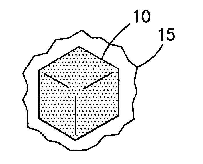
[0110] Diamond particles of 40 / 50 mesh were covered with a thin film of an acrylic binder.

[0111] The binder covered diamond was then mixed with a powdered metallic alloy containing B, Ni, Cr, Si, having an average particle size of about 325 mesh, and sold under the trade name NICHROBRAZ LM® (Wall Colomnoy). The result was a braze powder wrapped diamond. These coated particles were then mixed with fine powder of Al2O3. The mixture was heated in a vacuum furnace held at 10−5 torr to a maximum temperature of about 1005° C. for approximately 17 minutes to assure that the metallic alloy coating became molten and liquefied and flowed around the diamond particles wetting them. The mixture was then cooled and retrieved from the furnace. After separating the diamond particles from Al2O3, a number of coated particles were mixed with a cobalt powder and sintered in a hot press to form rectangular segments. Some of these segments were broken by bending with pliers. The fractured surface was th...

example 2

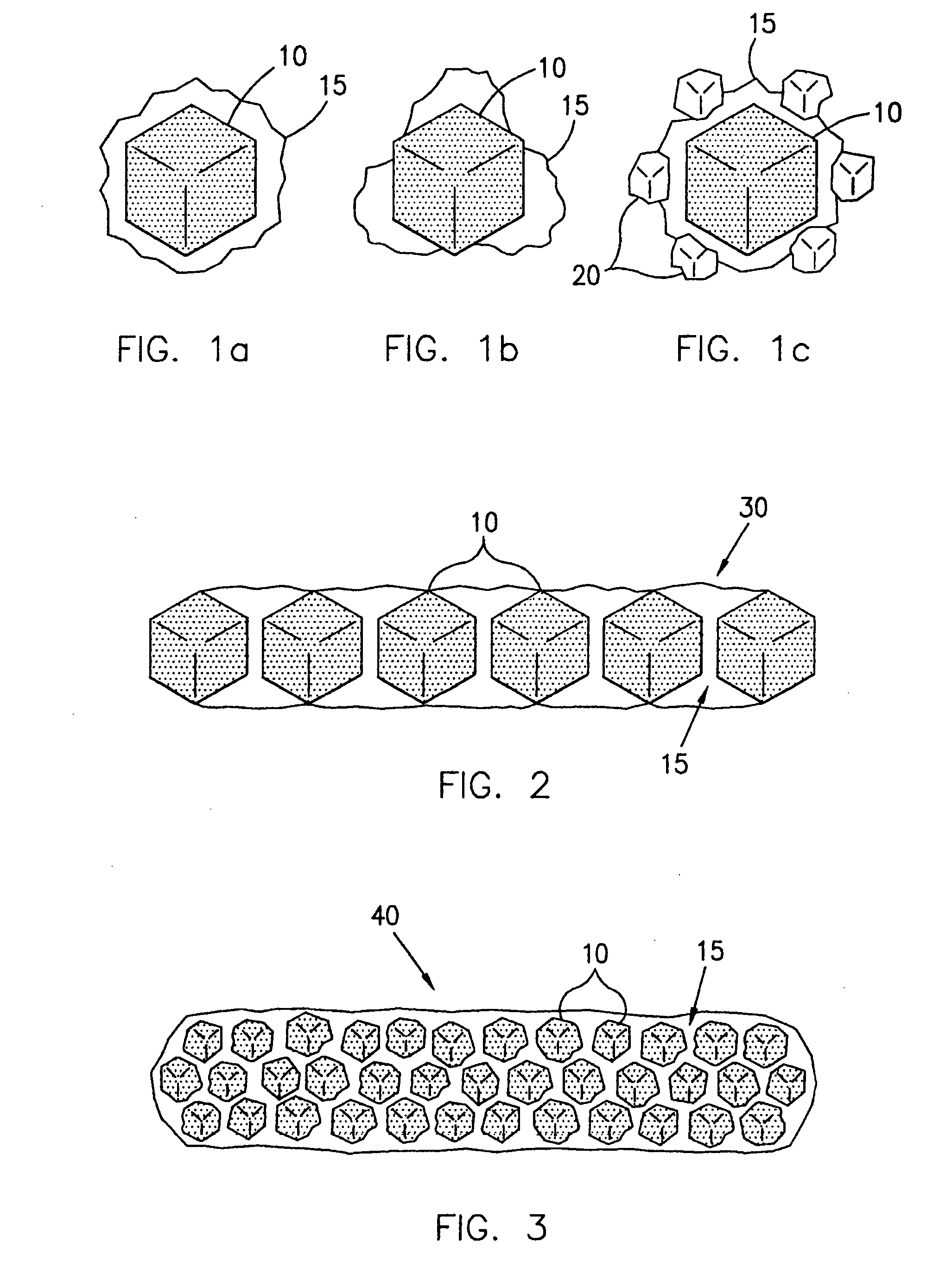
[0112] The same procedure as outlined in Example 1 was followed, but the Al2O3 separator powder was replaced with diamond particles having an average mesh size of from about 325 to about 400 mesh. During the heating process, the smaller diamond particles were wetted by the braze alloy coating, and became chemically bonded to the outside of the coated diamond particle. Thus, coated diamond particles having a chemically bonded metallic alloy shell with smaller diamond particles further bonded to the outside of the shell were produced. These “spiky” coated particles were incorporated into a cobalt matrix and fracture tested as above with similar results achieved.

example 3

[0113] The process of Example 2 was followed, but the smaller diamond particles were replaced with particles of SiC. The process yielded a coated diamond particle having ceramic particles bonded to the outside of the metallic coating similar to the diamond particles of Example 2. Moreover, the fracture testing yielded results similar to that of Examples 1 and 2.


PUM

PropertyMeasurementUnit
Strengthaaaaaaaaaa

Abstract

Methods of making superabrasive tools having improved retention of superabrasive particles in a metal matrix are provided. Such methods may include providing a substrate, providing superabrasive particles, chemically bonding the superabrasive particles with the metal matrix to a degree which holds the superabrasive particles in the metal matrix without substantially degrading the superabrasive particles, and metallurgically bonding the superabrasive particles to the substrate with the metal matrix.

Description

PRIORITY DATA [0001] This application is a continuation-in-part of U.S. patent application Ser. No. 11 / 223,790, filed Sep. 8, 2005, which is a continuation-in-part of U.S. patent application Ser. No. 11 / 009,370, filed Dec. 9, 2004, which is a continuation-in-part of U.S. patent application Ser. No. 10 / 627,441, filed Jul. 25, 2003, which is a continuation-in-part of U.S. patent application Ser. No. 10 / 254,057, filed Sep. 24, 2002, which has issued as U.S. Pat. No. 6,830,598, each of which is incorporated herein by reference.FIELD OF THE INVENTION [0002] The present invention relates to devices that incorporate superabrasive materials, and methods for the production and use thereof. Accordingly, the present invention involves the fields of chemistry, physics, and materials science. BACKGROUND OF THE INVENTION [0003] Various industries use chemical mechanical planarization (CMP) for polishing certain work pieces. Specifically, the computer manufacturing industry has begun to rely heavi...

Claims


Application Information

Patent Timeline
IPC IPC(8): B24D3/02B22F1/17B24B1/00B24D3/00B24D18/00B24D99/00C09K3/14C22CE21B10/00
CPCB22F1/025B22F2005/001B22F2998/10B24D3/08B24D18/00C09K3/1445C22C26/00B22F1/0059C22C1/05B22F3/10B22F1/17
Inventor SUNG, CHIEN-MIN
Owner SUNG CHIEN MIN
Features
  • Generate Ideas
  • Intellectual Property
  • Life Sciences
  • Materials
  • Tech Scout
  • Unparalleled Data Quality
  • Higher Quality Content
  • 60% Fewer Hallucinations
Learn More