Distance sensor and method for detecting a distance

a distance sensor and distance detection technology, applied in the field of distance measurements, can solve the problems of limiting the bandwidth of the system, unable to operate with sufficient reliability in all fields of application, and deviations from the theory, so as to achieve the effect of increasing reliability and/or precision

Active Publication Date: 2006-09-28
VOLKSWAGEN AG
View PDF9 Cites 62 Cited by
  • Summary
  • Abstract
  • Description
  • Claims
  • Application Information

AI Technical Summary

Benefits of technology

[0017] It is an object of the present invention to provide a distance sensor and a method for detecting a dis

Problems solved by technology

However, different problems result in deviations from the theory.
However, this limits the bandwidth of the system.
It is of disadvantage in the measuring system illustrated above that it cannot operate with sufficient reliability in all fields of application.
When an airbag is not triggered, this might have fatal consequences, as does a malfunction in road recognition.
The 3D-CMOS distance measuring systems illustrated above, for example, only fulfill the reliability criteria required entailing high complexity because they are susceptible to fog or rain situations and thus

Method used


Image

  • Distance sensor and method for detecting a distance
  • Distance sensor and method for detecting a distance
  • Distance sensor and method for detecting a distance

Examples


Embodiment Construction

[0040] With regard to the subsequent description, it is pointed out that same elements or elements corresponding to one another are provided with same or similar reference numerals in the figures and that a repeated description is omitted.

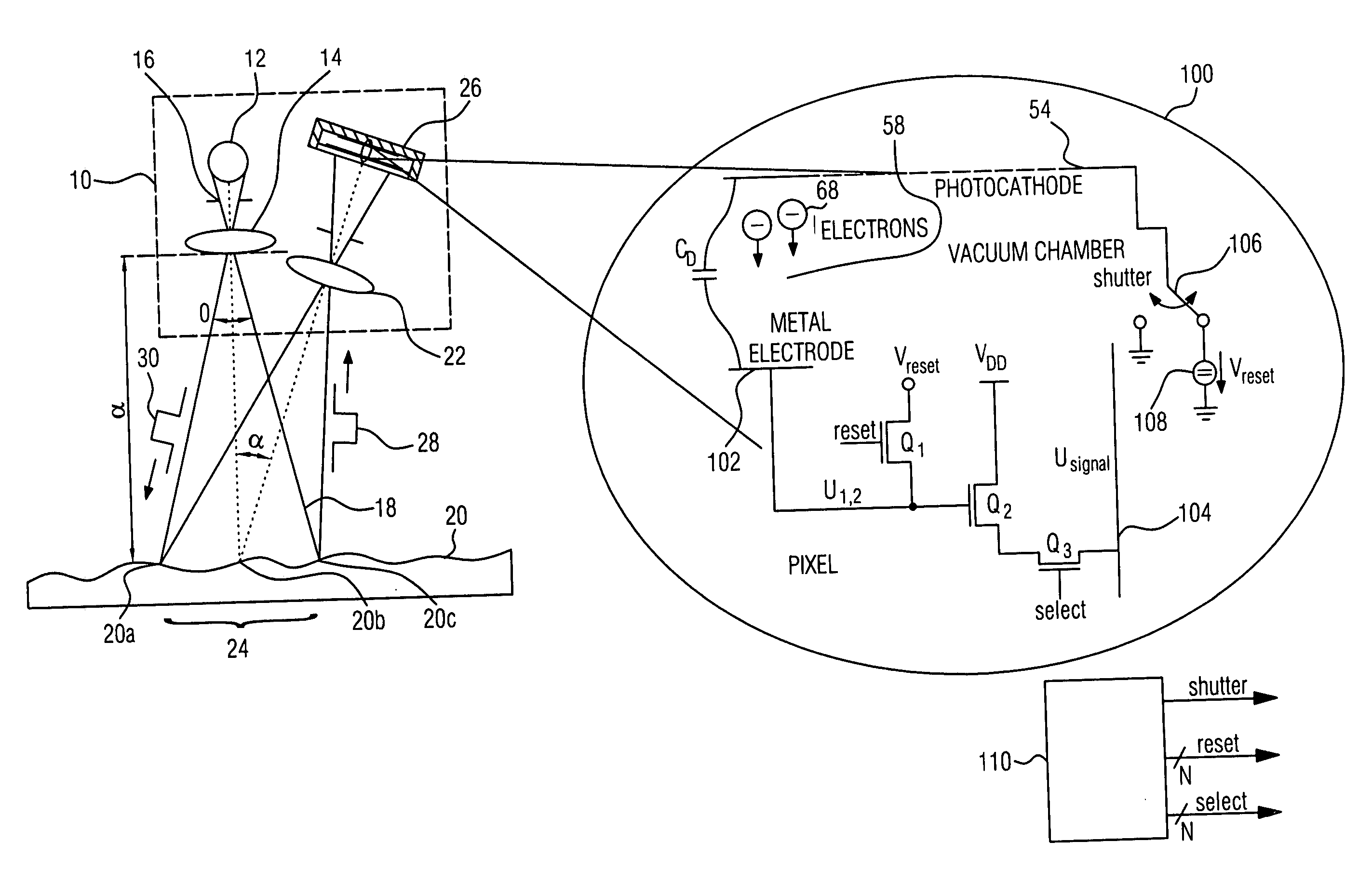
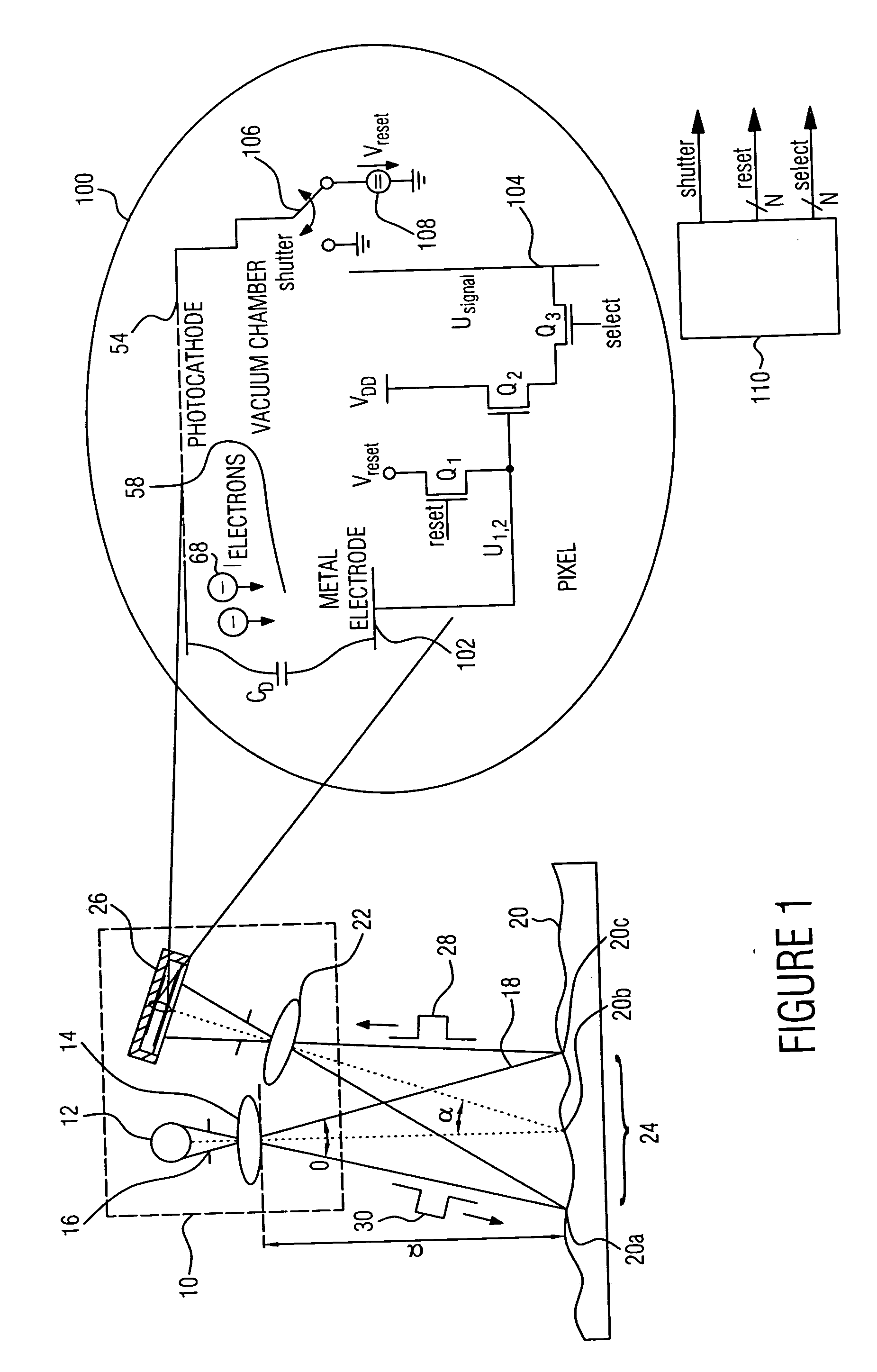
[0041]FIG. 1 shows a 3D distance sensor according to an embodiment of the present invention. The 3D distance sensor is generally indicated by 10. The distance sensor includes a radiation source 12 for electromagnetic radiation, irradiation optics 14 for expanding a beam 16 from the radiation source 12 to become an expanded light bundle 18 onto an object 20, receiving optics 22 for imaging the region 24 of the object 20 irradiated by the radiation source 16 onto a light-sensitive detection plane of pixel detection means 26 also included in the distance sensor 10.

[0042] The radiation source 12 could be any radiation source, such as, for example, an LED or a laser. To simplify the illustration, it will be assumed that the radiation source 12 is a la...


PUM


Abstract

An indirect detection of the reflected radiation pulses, when measuring a distance by means of the photoeffect, allows considerably expanding the usability of the distance sensor and the distance measuring method, wherein the adaption to a new field of application only requires little design changes. Since in the external photoeffect the photoelectrons are ejected from the material irradiated photon by photon or quantum by quantum and the photons, when being ejected, only require a certain minimum energy and correspondingly the radiation used for irradiation only requires a sufficiently small wavelength, the external photoeffect allows detecting radiation over a large spectral range. When interferences occur in a certain wavelength range in a certain field of application, the operating wavelength range of the distance sensor technology may at first simply be set to another spectral range by using such an irradiation source having a spectrum outside the spectral range containing the interferences.

Description

CROSS-REFERENCE TO RELATED APPLICATION [0001] This application is a continuation of copending International Application No. PCT / EP03 / 12007, filed Oct. 29, 2003, which designated the United States and was not published in English, and is incorporated herein by reference in its entirety.BACKGROUND OF THE INVENTION [0002] 1. Field of the Invention [0003] The present invention relates to distance measurements in general and to a distance measurement as may be employed in 3D cameras in particular. [0004] 2. Description of Prior Art [0005] Image-capturing sensors offer a way of detecting a depth in a non-tactile way. This may, for example, take place using extremely short shutter times in near-infrared (NIR) light pulse runtime measurements. Today, for example, CMOS cameras having active NIR illumination detecting three-dimensional object information by means of pulsed electromagnetic radiation are available. Three-dimensional distance images of the object captured are generated by captur...

Claims


Application Information

Patent Timeline
IPC IPC(8): G01N21/86G01S7/481G01S7/4863G01S17/894G01S17/931
CPCG01S7/481G01S7/4863G01S17/89G01S17/936G01S17/931G01S17/894
Inventor SCHREY, OLAFBROCKHERDE, WERNERHOSTICKA, BEDRICH
Owner VOLKSWAGEN AG
Why Eureka
Try Eureka