System and method for power ratio determination with common mode suppression through electric field differencing

a technology of power ratio and electric field, applied in the field of detecting the power of electromagnetic signals, can solve the problems of exceeding the maximum sensitivities of such conventional electric field sensing systems, requiring spectrometer sensitivities not available in laboratory spectrometers, and challenging the maximum sensitivities, so as to improve the noise performance, increase the gain of the receiver, and improve the effect of noise performan

Active Publication Date: 2006-10-12
THE BF GOODRICH CO
View PDF6 Cites 12 Cited by
  • Summary
  • Abstract
  • Description
  • Claims
  • Application Information

AI Technical Summary

Benefits of technology

[0009] Embodiments of the present invention therefore provide an improved system and method for processing a signal through electric-field differencing. In accordance with embodiments of the present invention, a receiver assembly includes a highly-sensitive electric-field detector. Detection and amplification is applied to the difference between sample and reference electric fields. In this regard, by differencing the sample and reference electric fields, the system of embodiments of the present invention removes the large common mode (average) electric field component, thereby increasing the gain of the receiver and accordingly providing superior noise performance, particularly when voltage noise of a post receiver amplifier operates as the dominant source of noise. As such, the system and method of embodiments of the present invention improve the noise performance of prior electric field sensing techniques.

Problems solved by technology

Nonetheless, in various contexts, the maximum sensitivities permitted by such conventional electric-field sensing systems are being challenged, and even exceeded.
However, measurements on such samples require spectrometer sensitivities not available in today's laboratory spectrometers.

Method used


Image

  • System and method for power ratio determination with common mode suppression through electric field differencing
  • System and method for power ratio determination with common mode suppression through electric field differencing
  • System and method for power ratio determination with common mode suppression through electric field differencing

Examples


Embodiment Construction

[0018] The present invention now will be described more fully hereinafter with reference to the accompanying drawings, in which preferred embodiments of the invention are shown. This invention may, however, be embodied in many different forms and should not be construed as limited to the embodiments set forth herein; rather, these embodiments are provided so that this disclosure will be thorough and complete, and will fully convey the scope of the invention to those skilled in the art. Like numbers refer to like elements throughout.

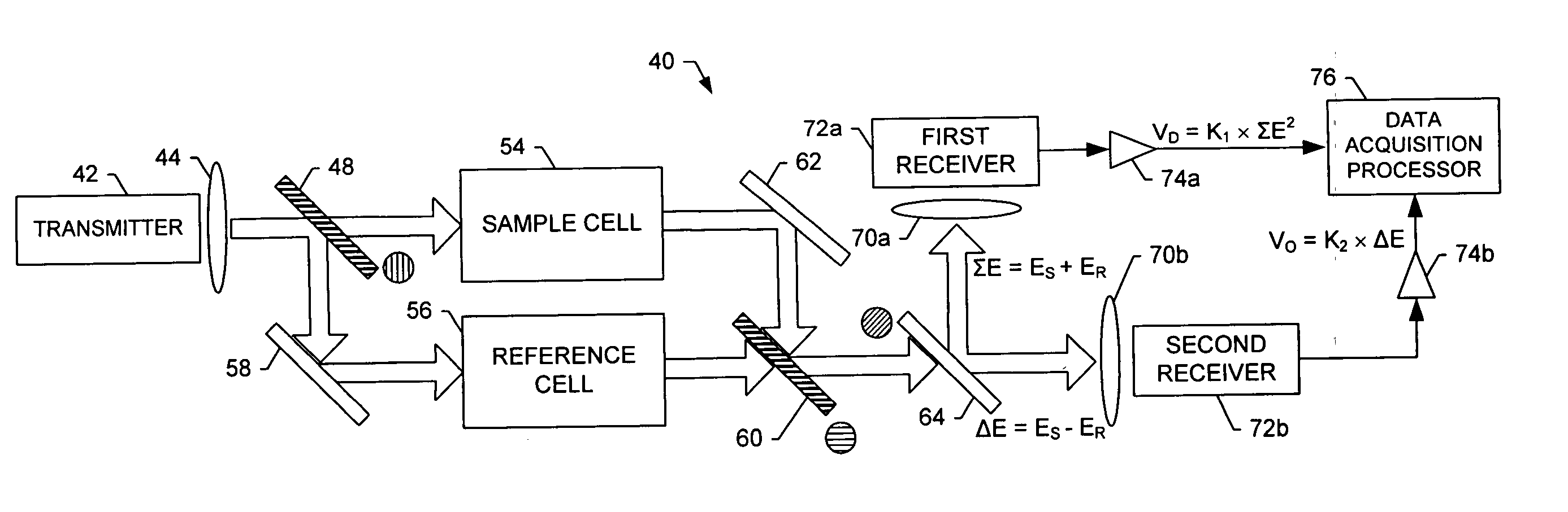
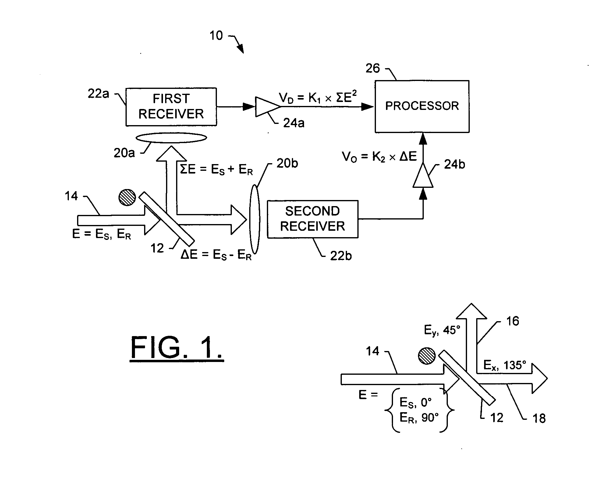
[0019] Referring to FIGS. 1 and 2, a receiver assembly 10 and method for receiving and processing a signal beam of light are shown in accordance with one embodiment of the present invention. As shown, the assembly includes an analyzer 12 for receiving a signal comprising a beam of light 14 having a first, or sample, component with a sample electric field ES and a first polarization, as shown in block 30. In addition, the beam has a second, or reference, ...


PUM


Abstract

A system for processing signals includes a receiver assembly for receiving a signal. The signal has a sample component with a sample electric field and a sample polarization, and has a reference component with a reference electric field and a reference polarization. The receiver assembly includes an analyzer for polarimetrically processing the signal, including differencing the signal to generate a difference electric field proportional to the difference of the sample and reference electric fields. By polarimetrically differencing the signal, the analyzer reduces the magnitude of the common-mode signal at the difference signal receiver. The receiver assembly includes an electric-field detector for measuring the difference electric field such that the reduction in common-mode amplitude decreases the noise equivalent power of the electric-field detector. One advantage of the present invention, then, is the reduction of noise equivalent power of the electric-field detector when measuring small variations in large electric fields.

Description

FIELD OF THE INVENTION [0001] The present invention generally relates to detecting the power of electromagnetic signals and, more particularly, to detecting the ratio of power of electromagnetic signals propagated through two media of different transmissions. Detection of trace amounts of absorbed power is enhanced by the method of this invention enabling the field of spectroscopy with greatly improved sensitivity. The invention enhances the sensitivity of heterodyne detection of electric field differences by reducing the magnitude of large common mode field amplitudes for any differential-measurement application, particularly in the Terahertz region of the electromagnetic spectrum. BACKGROUND OF THE INVENTION [0002] In many contexts it is desirable to detect electromagnetic radiation signals, such as in spectroscopy, refractive index measurements or the like. Conventionally, such radiation may be detected by means of a power detector whose output voltage is proportional to input po...

Claims


Application Information

Patent Timeline
Patent Type & Authority Applications(United States)
IPC IPC(8): G01J1/04
CPCG01J3/42G01N21/21G01J3/447G01N21/3581
Inventor ABREU, RENEGROTTS, JEFFREYMAJEWSKI, ALEXANDER J.
Owner THE BF GOODRICH CO
Why Eureka
Try Eureka