Stationary co-axial multi-rotor wind turbine supported by continuous central driveshaft

a coaxial, wind turbine technology, applied in the direction of machines/engines, renewable energy generation, greenhouse gas reduction, etc., to achieve the effect of less required stiffness, less cost, and less required stiffness

Inactive Publication Date: 2006-10-19
SELSAM DOUGLAS SPRIGGS
View PDF10 Cites 49 Cited by
  • Summary
  • Abstract
  • Description
  • Claims
  • Application Information

AI Technical Summary

Benefits of technology

[0059] If the wind resource in a given location rarely changes direction, the ability to aim our co-axial, multi-rotor array of modern, high TSR (tip speed ratio), horizontal axis-type rotors, loses its importance. Permanent placement, in the best orientation for overall energy capture, allows support from more than one point, thereby allowing a longer driveshaft with less required stiffness, supporting more attached rotors, and thereby producing more power than our prior art cantilevered versions, at less cost.

Problems solved by technology

This practice has resulted in disproportionately heavy blades and lowered rotational speed (low RPM), which have then required more gearing to drive a high-speed generator.
With wind energy now the fastest-growing segment of the energy industry, the traditional approach of meeting the demand for more powerful turbines by further increasing rotor diameter, results in three major engineering limitations:
First, larger blades produce less power for the amount of material used.
Blade weight varies as the cube of diameter, power varies as the square of diameter; with increasing diameter, blade weight grows faster than power output, so larger blades are less economical.
Second, as rotor diameter increases, RPM drops: larger rotors turn slower, requiring more gearing to drive a generator.
Third, drivetrain torque, like blade weight, is a cubic function in relation to diameter, and so torque also increases disproportionately to power output as diameter increases.
Wear on gear teeth and bearings is a major cause of expensive downtime and repair.
Direct-drive, large-diameter, low RPM, permanent magnet ring generators are one effective, but expensive solution.
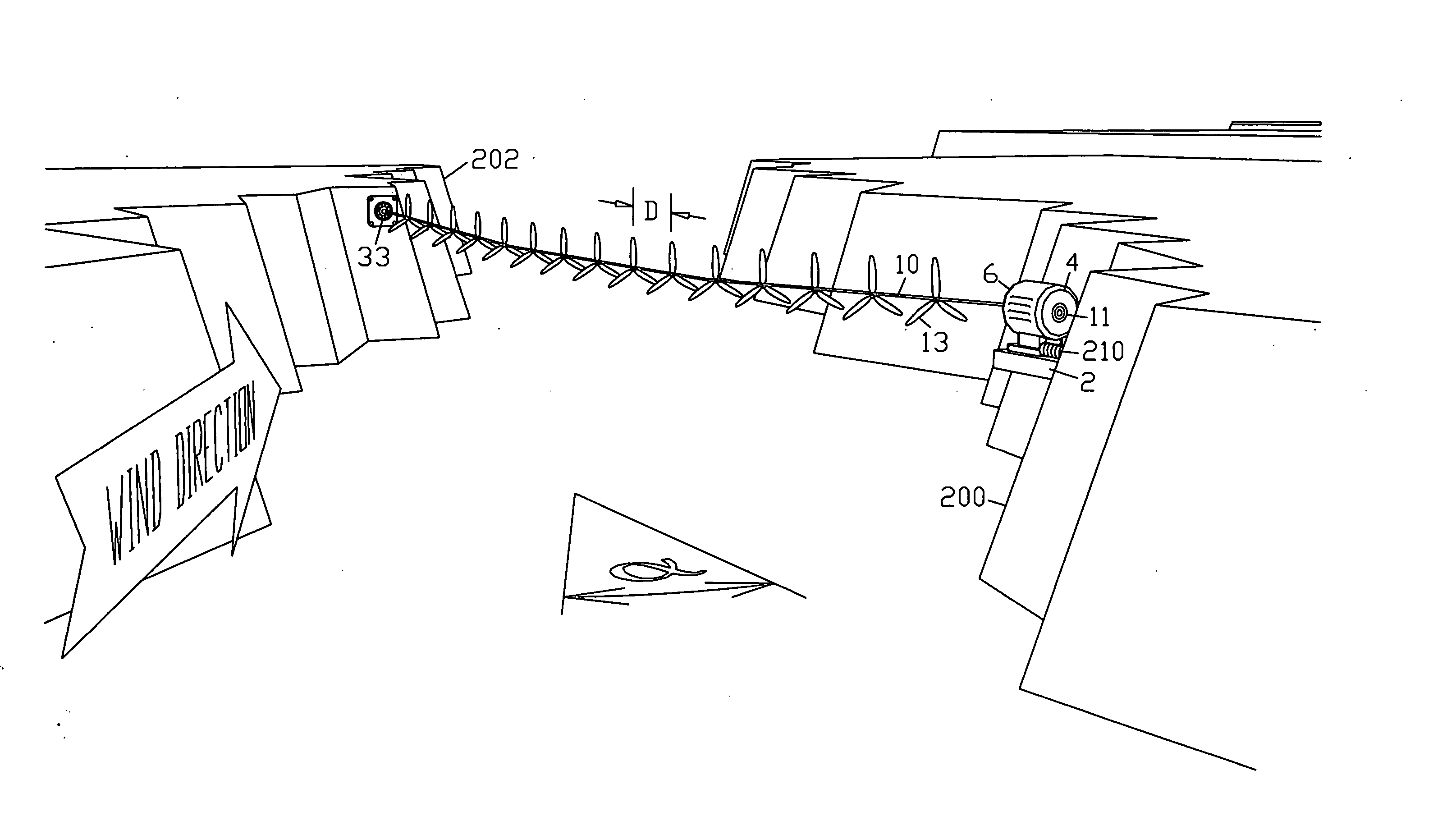
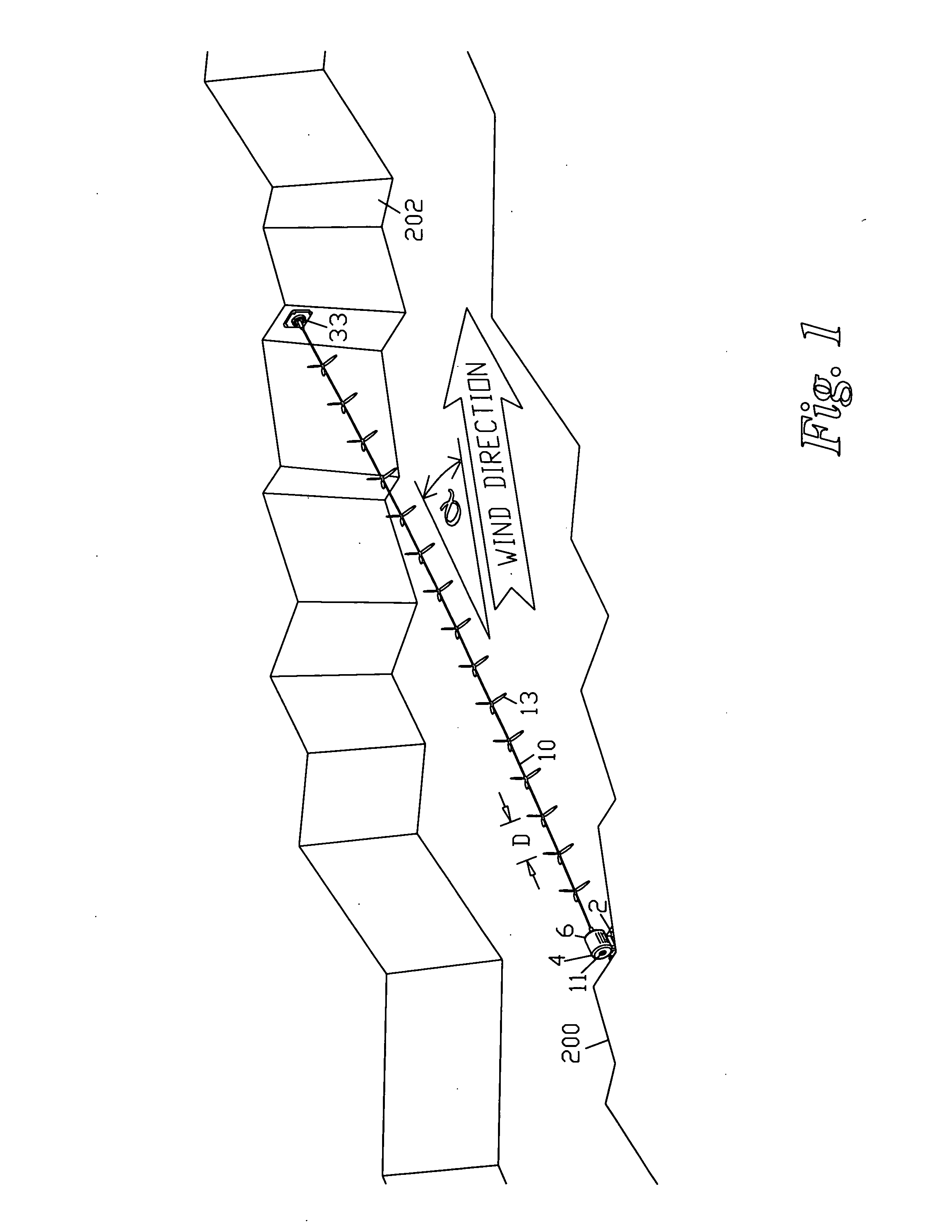
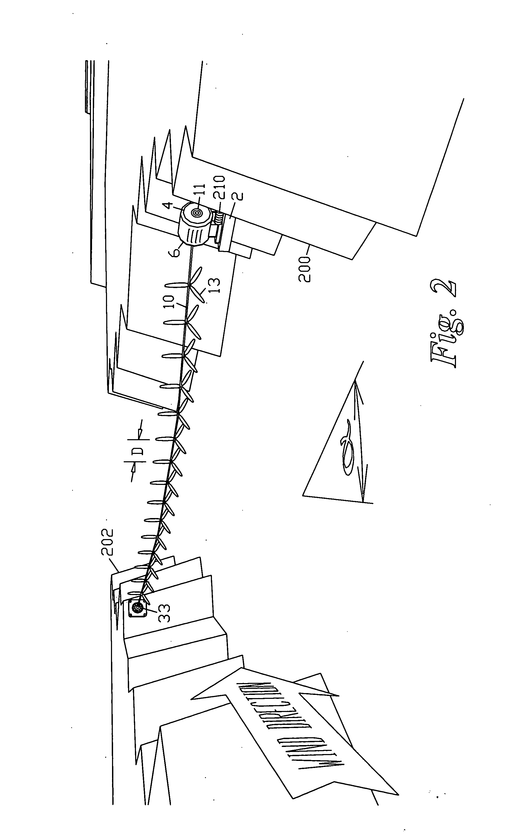
These methods provide for a longer driveshaft while preserving directional aim, but are still limited in the number of additional rotors that can be supported at effective spacing intervals.
The cantilevered driveshaft configuration demands high stiffness and light weight, limiting length.
Additional support means that allow a longer driveshaft while maintaining the ability to aim have been disclosed, but are still limited in their effectiveness.
Exact aim of the driveshaft however, while providing maximum power output, was not essential for at least useful power output.
The predominant wind resource at our test site prevails from within a narrow directional range, and this relatively unidirectional wind resource is common to most high wind locations.
Driveshaft power then, has been limited by the number, and effective spacing of the attached rotors, and by the angle and height of the driveshaft in relation to the instantaneous wind resource.
Like many fanciful wind turbine “inventions”, that are proposed but never actually built, this concept reveals a lack of real-world wind turbine experience:
Problems with this design include:
Low efficiency, drag-based operation: Harburg's design is restricted to low-speed rotation, due to the extremely low efficiency, low-speed, high-solidity rotors, featuring single-surface cloth sails with no defined airfoil shape, rather than blades, a 2000 year-old technology, and because of the aerodynamic drag of the lines attached to the rotor tips: At high speed, a line with a circular cross section has many times the aerodynamic drag of a streamlined shape of the same cross sectional area, such as a blade.
A modern high-speed, wind turbine blade is known to be sensitive to even dirt and bugs.
The addition of even small appendages, anywhere near the tip of a modern blade, is known to ruin the blade's performance, because the tip is the fastest-moving part of the blade.
Therefore a modern, high speed blade could not even be substituted for the sails in Harburg's design.
High-solidity rotors such as the farm water-pumping windmill have very low power coefficient (efficiency), because they transfer a high percentage of their potential energy capture to wake swirl; the wind itself is sent spinning in the opposite direction of the rotor spin, using up a sizable portion of the energy available.
The type of rotors required by Harburg's invention date back at least 2000 years to the Greek Islands, and are so inefficient that they do not even merit inclusion on this chart.
So Harburg is restricted to slow, inefficient, drag-based operation rather than modern, high speed lift-based operation by the fact that at high tip speeds, his torque transmitting lines would present many times the aerodynamic drag of the blades themselves, rendering them ineffective.
The greater radius of the outward-curving lines increases their absolute speed through the air, further increasing air resistance (drag), thereby further reducing efficiency, and further preventing the use of modern, high-speed blades.
This outward splay of the “lines” also would increase line tension—another factor tending to limit RPM.
Low RPM not suitable for economical electric power generation: Besides low efficiency, drag-based turbines are not considered good candidates for electricity generation, due to low rotational speed (RPM).
Standard generators require high-speed rotation, and lower initial RPM necessitates more gearing to drive the generator, raising costs and reducing reliability.
Direct-drive generators must be sized in reverse proportion to RPM, again raising costs for slowly rotating, drag-based turbines, if no gearbox is used.
This means that Harburg's slow rotation raises torque, raising tension on the “lines”, and causing more stress on the entire drivetrain.
The strength of the relatively small-diameter driveshafts supporting the armatures could be challenged by the twisting force of such high torque.
Cloth sails are known to be far slower and less efficient than rigid blades featuring airfoils having separate top and bottom surfaces, permanently and optimally shaped for their function.
Cloth sails are susceptible to icing and snow accumulation.
Cloth sails are not durable for long term operation, suffering from UV degradation from sunlight, and inevitable fraying from constant fluttering and flapping.
Cloth sails are not suited to permanent use in the wind, during all weather.
This again relegates Harburg's machine to the realm of low RPM and hence low efficiency.
Each rotor is comprised of 2 offset spars with a sail stretched between, to comprise a triangular blade that, again, is widest at the tip, again mandating low RPM, and low efficiency (Such rotors are so inefficient that they do not even appear on the chart of FIG. 38) Again, the notion that a sail made of flexible sheet material is somehow superior to a modern, relatively rigid wind turbine blade with a shaped airfoil shows a lack of even rudimentary knowledge of modern wind energy technology.
McCauley's wide-tipped sails would have low efficiency and additionally, would provide a poor choice for generating electricity due to their low speed rotation (low RPM).
Non-optimal aim: McCauley requires in all claims that the wind vector be substantially parallel to the rods, and cites means for moving one end of the apparatus, to insure that this aim, exactly parallel to the wind, is maintained at all times. His presumption that aiming the rods parallel to the wind would result in highest output shows a lack of knowledge of wind shadow and wake effects.
The combination of wake effects (from erroneously aiming directly into the wind), and inefficient, high solidity blades consisting of cloth sails stretched between spars, make it impossible for McCauley's alleged prototype to even approach the output of the long perfected H-80, let alone exceed it by 500%.
Power claims exceeding the Betz coefficient are a common, telltale symptom of fanciful, incompletely-developed turbine designs, based on a lack of understanding the prior art, revealing the accounts of measurements taken from prototypes built, as fraudulent.
McCauley's power claim is therefore false, and his accounts of an actual prototype are, again, of doubtful veracity.
The requirement that adjacent rotors be mutually offset by 90 degrees after all rotational slack has been taken up, again shows a lack of fundamental experience in wind energy.
Such continual angular rotational displacement would make such an angularly offset blade placement, as McCauly suggests, ineffective and irrelevant.
Since gearing is normally used to raise, not lower, RPM, this is a false conclusion based on a false assumption, opposite to reality, revealing no knowledge of the basic facts of wind energy and prior art wind turbines.
This concept however has the disadvantage of requiring separate bearings, generators and stationary support for each rotor, altogether requiring a heavy, complicated support structure, with a disproportionate amount of material required for the ducting surrounding each rotor.

Method used


Image

  • Stationary co-axial multi-rotor wind turbine supported by continuous central driveshaft
  • Stationary co-axial multi-rotor wind turbine supported by continuous central driveshaft
  • Stationary co-axial multi-rotor wind turbine supported by continuous central driveshaft

Examples


second embodiment

2. Stationary Co-Axial, Multi-Rotor-Turbine Spanning a Canyon, Supported from Three or More Points; FIG. 7:

[0093] The second embodiment is similar to the first embodiment, with the addition of one or more intermediate supports 220 for the driveshaft, such as a tower 90 supporting bearing 11 of FIG. 7, added to help elevate and stabilize the driveshaft, and reduce or even replace the required driveshaft stiffness and / or tension, Such intermediate supports may be additionally include one or more stabilizing structures such as horizontal guy wires 57, of FIG. 7. Slanting guy wires 55 could also be used as in FIG. 14. Such intermediate supports may also stabilize the driveshaft against the aggregate side thrust force exerted by the wind on the rotors. Guy wires 57 greatly aid in stabilizing the side-to side position of the driveshaft, and may prevent unwanted oscillations. Alternatively, such intermediate supports may be suspended from above (not illustrated). For example the intermedia...

third embodiment

3. Multiple Suspended Catenary Co-Axial, Multi-Rotor Turbines Spanning a Canyon; FIG. 6:

[0094] Multiple turbines similar to that of the first embodiment, may be placed across the same canyon. FIG. 6 shows such a multiplicity of turbines placed in a vertical array, in effect forming a wall of rotors through which the winds must pass to continue transit through the canyon. The result is a further multiplication of the total power output.

[0095] 4. Fourth Embodiment—FIG. 7: Similar to the third embodiment, multiple turbines span the canyon in a vertical array, but with staggered rotor spacing between adjacent driveshafts, allowing the driveshafts to be placed in closer mutual proximity, while yet avoiding blade strikes between adjacent turbines, which allows more driveshafts to be included in the array. The result is an increase in the total number of rotors, an increase in the aggregate solidity of the “wall of rotors”, and an increase in total power output.

5. Fifth Embodiment—FIG. ...

sixth embodiment

6. Multiple Suspended Catenary Co-Axial, Multi-Rotor Turbines Spanning Gap Between Buildings; FIG. 8:

[0101] This embodiment is similar to the fifth embodiment, a stationary, vertical array of co-axial, multi-rotor turbines, with rotors 13 staggered from one driveshaft 10 to the next, and intermediate supports 220, comprising tower 90, to help elevate and stabilize the driveshafts, allowing closer driveshaft spacing while avoiding blade strikes, for a higher density of turbines, yielding more power. Instead of a canyon, this array spans the gap between two buildings, strategically placed so that wind is focused or concentrated between them, with a line between a corner of each building falling at offset angle α (alpha) to the wind direction. The vertical array of Co-axial, multi-rotor turbines extends between these two corners. The buildings are angled so that the exterior side surfaces of the buildings serve as a narrowing funnel, to concentrate the wind before it reaches the turbin...


PUM


Abstract

Co-axial, multi-rotor wind turbines, producing more power than a single rotor of the same diameter, are made even more powerful by increasing driveshaft length and supporting the driveshaft from more than one point. Sacrificing the ability to aim, for the extra length to support additional rotors, results in a more powerful co-axial multi-rotor turbine, especially useful for areas with a predominantly unidirectional wind resource. Ideally the turbine is placed at an offset angle α (alpha) from the wind direction, which, in combination with proper spacing between rotors, allows fresh wind to reach each rotor, so that all rotors contribute toward rotation of the driveshaft. Placing the driveshaft under tension can raise critical speeds and reduce the number of intermediate supports required. This places the Earth or underlying substrate in compression, making it effectively part of the structure of the turbine, saving cost. Cross-axis and reversible blades may also be incorporated.

Description

CROSS-REFERENCE TO RELATED APPLICATIONS [0001] This patent application claims priority from U.S. Provisional Patent Application No. 60 / 712,792, filed Aug. 30, 2005, and is a continuation-in-part of U.S. patent application No. Ser. 10 / 810,375, filed Mar. 27, 2004, pending, and is a continuation-in-part of U.S. patent application Ser. No. 10 / 781,213, filed Feb. 17, 2004, issued as U.S. Pat. No. 7,008,172, which is a continuation-in-part of U.S. patent application Ser. No. 09 / 997,499, filed Nov. 23, 2001, issued as U.S. Pat. No. 6,692,230, which is a continuation-in-part of U.S. patent application Ser. No. 09 / 881,511, filed Jun. 14, 2001, issued as U.S. Pat. No. 6,616,402, the entireties of which are incorporated by reference herein and made a part of the present disclosure. BACKGROUND OF THE INVENTION [0002] This invention relates to windmills and wind turbines. (art unit 3745) PRIOR ART [0003] Power output of a wind turbine is proportional to the area swept by the blades. Traditional...

Claims


Application Information

Patent Timeline
Patent Type & Authority Applications(United States)
IPC IPC(8): F03D7/02
CPCF03D1/025F03D11/024F03D3/002F03D11/04F05B2210/16F05B2240/212F05B2240/91F05B2240/911F05B2240/917F05B2240/96F05B2250/25F05B2250/314F05B2260/40Y02E10/721Y02E10/728Y02E10/74Y02B10/30F03D1/065F03D15/10F03D13/20F03D9/25F03D15/20F03D9/30Y02E10/72F03D1/0658F03D7/0204
Inventor SELSAM, DOUGLAS SPRIGGS
Owner SELSAM DOUGLAS SPRIGGS
Why Eureka
Try Eureka