At the same time, however, a high beam power is required.
Materials other than
copper have not hitherto proven themselves for large editions.
Such an electromechanical oscillatory
system cannot be made arbitrarily fast because of the forces that must be exerted in order to engrave the cups.
This, however, still does not suffice for the short
engraving time of the printing cylinders required currently, since the
engraving time directly influences the actuality of the printing result.
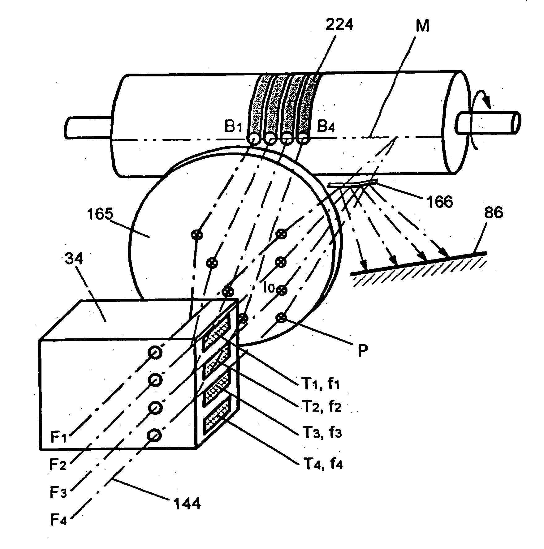
One problem that thereby arises is that cups having different volumes are generated in the individual lanes given the same tone value to be engraved, this occurring because of the different
engraving systems that are driven independently of one another and leading to differences in the individual lanes that the eye detects during later observation.
Since the geometry of the engraved cups is directly dependent on the shape of the
stylus, extremely high demands are also made of the geometry of the
diamond stylus which, as has been shown, can only be achieved with extremely high expense and with a high
rejection rate in the manufacture of the styli.
Moreover, the
diamond stylus is subject to wear since, when engraving a large printing cylinder having fourteen lanes, a circumference of 1.8 m and a length of 3.6 m given a screen of 70 lines / cm—which corresponds to a plurality of 4900 cups / cm2, a stylus must engrave approximately 20 million cups.
When one of the
diamond styli breaks off during the engraving of a printing cylinder, then the entire printing cylinder is unuseable.
On the one hand, this causes a considerable financial loss and, on the other hand, represents a serious loss of time since a new cylinder must be engraved, postponing the start of printing by hours.
All in all, electromagnetic engraving is well-suited for producing high-quality rotogravure cylinders; however, it has a number of weak points and is extremely complicated and one would like to eliminate these disadvantages with a different method.
Another
disadvantage of this operating mode of this electromechanical engraving is that texts and lines must also be reproduced in screened fashion, which leads to step-patterns in the contours of the written characters and the lines that the eye perceives as being disturbing.
This is one
disadvantage compared to the widespread
offset printing wherein this stepping can be kept an
order of magnitude lower, which can then no longer be perceived by the eye, and which leads to a better quality that rotogravure could hitherto not achieve.
In rotogravure, no stochastic screens can be generated wherein the size of the cups and the position of the cups can be randomly distributed corresponding to the tone value; this is not possible when engraving with the diamond stylus.
Due to the extremely high expense that is required for the hardware and
electronics,
electron beam engraving has hitherto not prevailed in practice for the engraving of
copper cylinders for rotogravure but only in the steel industry for surface engraving of what are referred to as textured drums for sheet
metal manufacture wherein textures are rolled into the sheets.
In this method, however, the remaining plastic is attacked by the
solvent of the ink in the printing process and is decomposed, so that only a low print run is possible.
This method has not proven itself in practice and has thus not been utilized.
One disadvantage of this method is that the arc lamps required for pumping the laser have a relatively short service life and must be replaced after approximately 500 hours of operation.
The engraving cylinder becomes unuseable given a failure of the pump
light source during the engraving.
This corresponds to a failure of the diamond stylus in electromechanical engraving and results in the same disadvantages.
A preventative replacement of the arc lamps is cost-intensive and work-intensive, particularly since one must count on the fact that the laser beam must be re-adjusted in position after the replacement of the lamps.
These lamp-pumped
solid-state lasers also have a very poor efficiency since the laser-active material absorbs only a slight fraction of the available energy from the pump source, i.e. from the
arc lamp here, and converts into
laser light.
Particularly given high laser powers, this means a high
electrical connection cost, high operating costs for electrical energy and cooling and, in particular, a considerable expense for structural measures due to the size of the laser and the cooling unit.
The
space requirements are so high that the laser unit must be located outside the
machine for space reasons, this in turn being accompanied by problems in bringing the laser output onto the surface of the printing cylinder.
A critical disadvantage of this method is that
zinc is significantly softer than
copper and is not suitable as a surface material for printing cylinders.
Since the doctor blade with which the excess ink is removed before printing in the
printing press is a steel blade, the
zinc surface is damaged after a certain time and the printing cylinder becomes unuseable.
Printing forms having a
zinc surface are therefore not suitable for high press runs.
Chrome does not adhere to zinc as well as it adheres to copper and what is referred to as “hot
chrome plating”, which is successfully employed given copper cylinders in order to achieve an optimum adhesion of the
chromium on the copper, is not possible given zinc since the zinc would thereby melt.
Since the chrome layer does not adhere very well on the zinc, it is likewise attacked by the doctor blade, which leads to a relatively early failure of the printing cylinders.
Such a power, however, cannot be produced with the laser arrangement described above.
Such a laser arrangement, which is composed of a single
solid-state laser, in fact makes it possible to process rotogravure cylinders having a zinc surface; if, however, one wishes to utilize the advantages of the copper surface and stay with copper cylinders and engrave these with a laser, the
high power density required for penetration into the surface of the copper and the
high energy required for melting the copper must be inevitably exerted.
This, however, has not hitherto been successfully done with a
solid-state laser.
Even if the power of the solid-state lasers were to be driven up or if a plurality of solid-state lasers were directed onto the same cup or parts thereof, it would therefore not be possible to satisfactorily engrave copper cylinders for rotogravure with such a laser because the precision of the laser beam, as offered by the
electron beam, required for generating the fine structures cannot be achieved.
If the laser power were increased given this apparatus, then a further problem would arise: the focusing of high
radiant intensity into optical fibers is, as known, difficult.
If one wishes to avoid this, however, the
fiber diameter would have to be enlarged which, however, in turn has the disadvantage that the
fiber diameter would have to be imaged onto the processing material with even greater demagnification.
This has a disadvantageous influence on the required
power density and on the exact dot size.
Since, however, the
diameter of the processing spot and the energy of the beam determine the size of the cup, it then becomes difficult to make the cup size as exactly as required by the desired tone value.
When this is not the case, the cup size changes and the cylinder becomes unuseable.
This cannot be compensated by varying the size of the processing spot since it is not possible to adequately vary the processing spot in shape.
Further, a complicated modulator is required given such an arrangement.
As known, modulators for extremely high laser powers are slow, this leading to a reduction of the modulation frequency and, thus, of the engraving frequency.
When, however, the engraving frequency is too low, the energy diffuses into the environment of the processing spot on the processing surface without
cutting out a cup.

