Fluoropolyether compound

a fluoropolyether and compound technology, applied in the field of fluoropolyether compound, can solve the problems of low viscosity, difficult application, and difficulty in obtaining oh groups per unit volume, and achieve the effects of low vapor pressure, low viscosity, and less problem in deterioration

Inactive Publication Date: 2006-11-09
ASAHI GLASS CO LTD
View PDF5 Cites 26 Cited by
  • Summary
  • Abstract
  • Description
  • Claims
  • Application Information

AI Technical Summary

Benefits of technology

[0027] According to the present invention, a novel fluoropolyether compound useful as e.g. a lubricant, a surface modifier or a surfactant, is provided. The fluoropolyether compound of the present invention has a

Problems solved by technology

In an attempt to accomplish a low vapor pressure, it has been attempted to increase the molecular weight, but when it is attempted to increase the molecular weight of the compound (I), there has been a problem that the viscosity increases remarkably, whereby its application tends to be difficult.
Further, there has been a problem that the proportion of —CH2OH groups per unit volume becomes low by the increase of the molecular weight, whereby the self-replenishing property tends to deteriorate.
This unit is a unit which causes the decomposition reacti

Method used


Image

  • Fluoropolyether compound
  • Fluoropolyether compound
  • Fluoropolyether compound

Examples


example 1

Example for Esterification Reaction

[0093] Ethylene oxide is added to a triol represented by the formula HC(CH2OH)3 by a known method, and then R-225 (50 g) and NaF (2.88 g) are put in a flask, and nitrogen is bubbled with vigorous stirring while the internal temperature is maintained at 25° C. to obtain the following compound (D2-1). FCOCF(CF3)OCF2CF(CF3)O(CF2)3F (34.3 g) is dropwise added thereto over a period of 1.0 hour, while the internal temperature is maintained at a level of at most 10° C. After completion of the dropwise addition, the mixture is stirred at room temperature for 24 hours, whereupon a crude liquid is recovered. Further, the crude liquid is subjected to filtration under reduced pressure, and the recovered liquid is dried for 12 hours in a vacuum drier (100° C., 666.5 Pa (absolute pressure)). The crude liquid thereby obtained is dissolved in R-225 (100 mL) and washed three times with a saturated bisodium carbonate solution (1,000 mL) to recover an organic phase....

example 2

Example for Fluorination of Compound (D3-1) Obtained in Example 1

example 2-1

Example Wherein the Solvent for the Reaction is R-113

[0097] Into a 500 mL autoclave made of hastelloy, R-113 (312 g) is added, stirred and maintained at 25° C. At the gas outlet of the autoclave, a condenser maintained at 20° C., a NaF pellet-packed layer and a condenser maintained at −20° C. are installed in series. Here, from the condenser maintained at −20° C., a liquid-returning line to return the condensed liquid to the autoclave, is installed. After blowing nitrogen gas for 1.0 hour, fluorine gas diluted to 20 mol % with nitrogen gas (hereinafter referred to as 20% fluorine gas) is blown for one hour at a flow rate of 16.97 L / hr.

[0098] Then, while 20% fluorine gas is blown at the same flow rate, a solution having the product (D3-1) (15 g) obtained in Example 1 dissolved in R-113 (200 g), is injected over a period of 11 hours.

[0099] Then, 6 mL of a R-113 solution is injected, while 20% fluorine gas is blown at the same flow rate. Further, nitrogen gas is blown for 1.0 hour. ...


PUM

PropertyMeasurementUnit
Percent by massaaaaaaaaaa
Concentrationaaaaaaaaaa
Viscosityaaaaaaaaaa

Abstract

It is to provide a compound which has a low vapor pressure and low viscosity, which is less problematic in deterioration during its use and which is useful as e.g. a lubricant, a surface modifier or a surfactant.
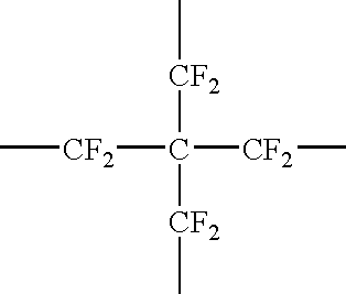
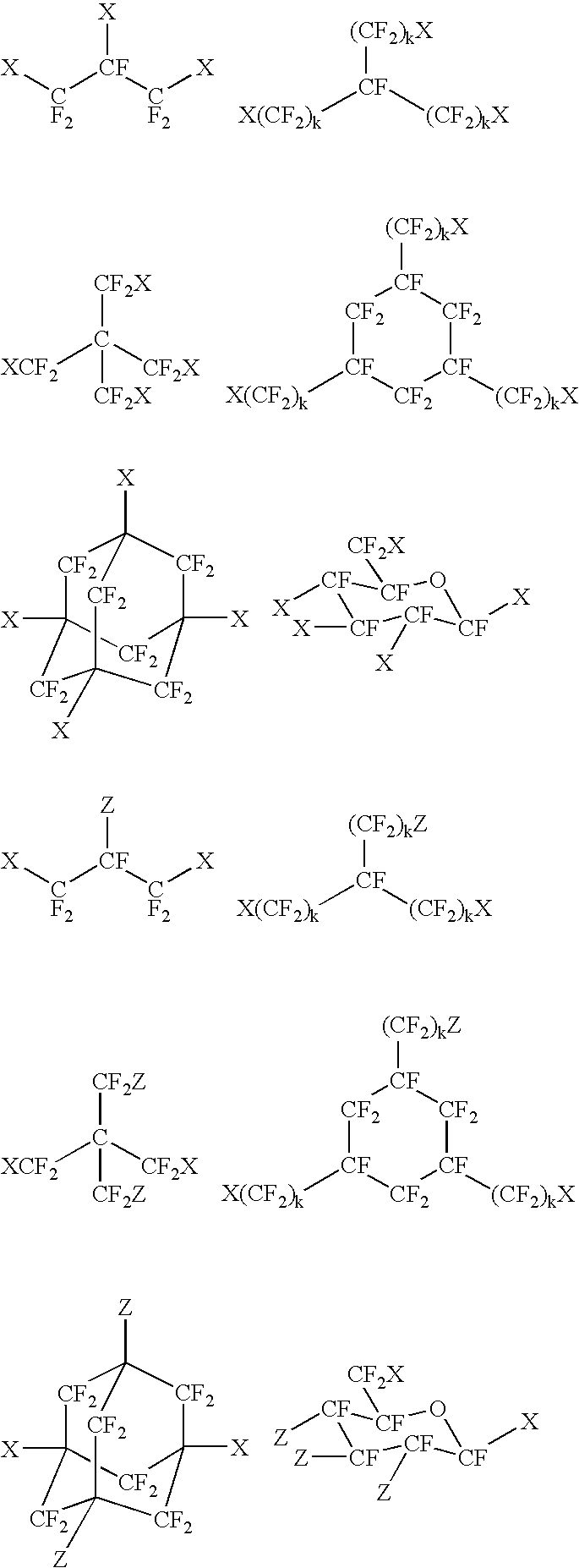
A fluoropolyether compound represented by the formula (X—)xY(-Z)z, wherein X is a group represented by the formula HO—(CH2CH2O)a.(CH2CH(OH) CH2O)b—(CH2)c—CF2O(CF2CF2O)d— (wherein “a” is an integer of from 0 to 100, b is an integer of from 0 to 100, c is an integer of from 1 to 100, and d is an integer of from 1 to 200), Z is a group represented by the formula RFO(CF2CF2O)g— (wherein RF is e.g. a C120 perfluoroalkyl group having an etheric oxygen atom inserted between carbon-carbon atoms, and g is an integer of from 3 to 200), Y is e.g. a (x+z) valent perfluorinated saturated hydrocarbon group, x is an integer of at least 2, z is an integer of at least 0, and (x+z) is an integer of from 3 to 20.

Description

TECHNICAL FIELD [0001] The present invention relates to a novel fluoropolyether compound useful as e.g. a lubricant, a surface modifier or a surfactant. BACKGROUND ART [0002] Perfluorinated polyether compounds are widely used as e.g. a lubricant, a surface modifier or a surfactant. For example, as a compound having its terminal group converted to —CH2OH, a compound represented by the following formula (I) (wherein each of h and i is an integer of at least 1) has been known (for example, Non-Patent Document 1): HO—CH2CF2O—(CF2CF2O)h—(CF2O)i—CF2CH2OH   (I) [0003] It is known by the document that the surface having a coating film formed by application of the compound (I) on the substrate surface, has a nature (self-replenishing property) such that when a part of the coating film becomes defective, the compound (I) around the defective portion will cover the defective portion to replenish the defective portion. Further, it is known that a —CH2OH group present at the molecular terminal o...

Claims


Application Information

Patent Timeline
IPC IPC(8): C08G65/321C08G65/323C08G65/337C08L71/02C10M105/54C10M107/38C11D1/00
CPCC08G65/323C08G65/337C08L71/02C11D1/004C10M107/38C10M2211/0406C10M2213/043C10M105/54
Inventor SHIRAKAWA, DAISUKEOHARU, KAZUYAOKAZOE, TAKASHI
Owner ASAHI GLASS CO LTD
Why Eureka
Try Eureka