Smart materials: strain sensing and stress determination by means of nanotube sensing systems, composites, and devices

Inactive Publication Date: 2006-11-09
RICE UNIV
View PDF14 Cites 101 Cited by
  • Summary
  • Abstract
  • Description
  • Claims
  • Application Information

AI Technical Summary

Benefits of technology

[0014] In some embodiments of the present invention, the sensor comprises a mat, film, or “buckypaper” of carbon nanotubes. In some embodiments, the carbon nanotubes are dispersed and/or blended with another material, possibly forming a composite material. In some embodiments, the carbon nanotubes are refined and/or chemically or physically modified in an effort to tune their ele

Problems solved by technology

However, Raman spectroscopy is an arduous process requiring sensitive, sophisticated equipment.
Moreover, this technique relies on perturbations in the vibrational modes of carbon nanotubes, not merely on perturbations of the

Method used


Image

  • Smart materials: strain sensing and stress determination by means of nanotube sensing systems, composites, and devices
  • Smart materials: strain sensing and stress determination by means of nanotube sensing systems, composites, and devices
  • Smart materials: strain sensing and stress determination by means of nanotube sensing systems, composites, and devices

Examples


example 1

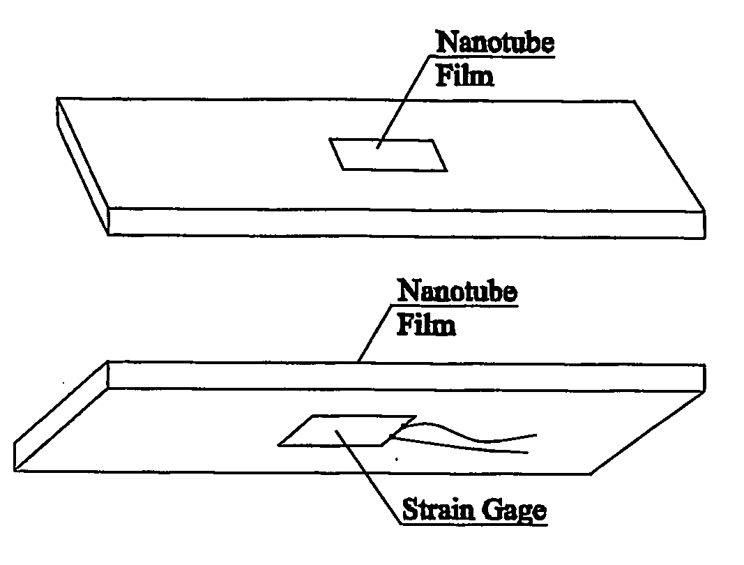
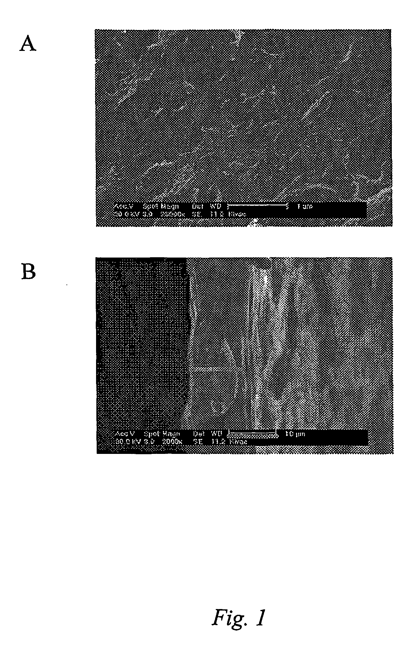
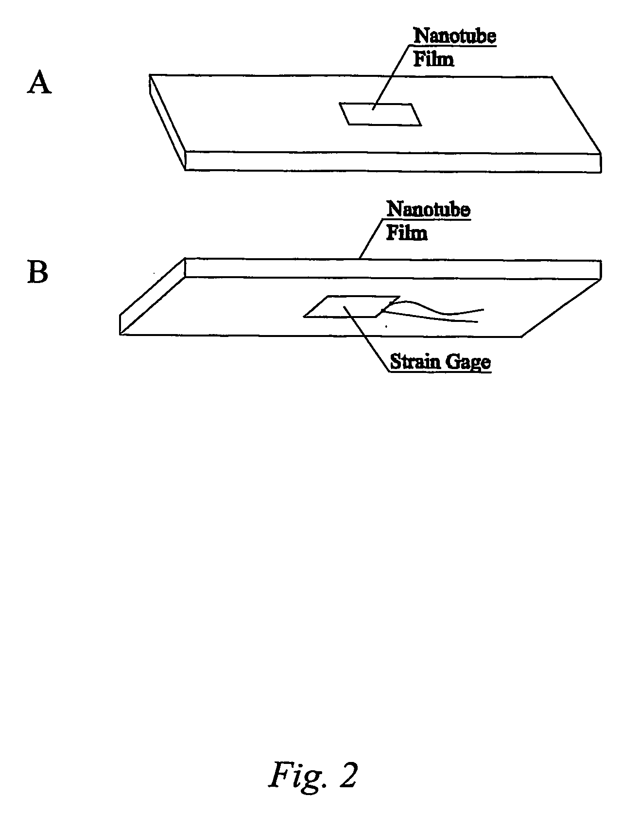
[0062] This Example serves to illustrate embodiments of the present invention in which add-on sensors comprising a film (i.e., “buckypaper”) are used to sense stress and strain. The results put forth in the present Example can be found in a forthcoming publication by Applicants. See Dharap et al., “Nanotube film based on single-wall carbon nanotubes for strain sensing,” Nanotechnology, 15(3), pp. 379-382 (2004).

[0063] A carbon nanotube film is produced by mixing unpurified SWNTs (obtained from Carbon Nanotechnologies, Inc.) with 0.25 mg / mL N,N-Dimethylformamide (DMF). The mixture is filtered by a 0.2 mm Teflon membrane and dried. The film (buckypaper) is peeled from the filter after drying. Then the film is further dried for 24 hours under vacuum and heat. FIG. 1(a) shows a scanning electron microscope (SEM) image of the carbon nanotube film where it can be seen that the film is composed of mechanically entangled, randomly oriented nanotube bundles that impart it with isotropic ele...

example 2

[0069] This Example serves to illustrate how carbon nanotube sensing elements can be incorporated into layered materials like laminates to sense mechanical conditions in multiple directions.

[0070] Referring to FIG. 5a (FIG. 5b shows an exploded view), a film 501 comprising carbon nanotubes aligned in one direction is laminated to a film 503 comprising carbon nanotubes oriented in a direction different from that in film 501. Such lamination may comprise an additional laminating agent 502. The films comprising the aligned carbon nanotubes also comprise mylar, although the carbon nanotubes could be used by themselves or with another material. In this particular Example, however, the carbon nanotubes were aligned in the mylar via an extrusion process whereby a blend, comprising about 20 wt. % carbon nanotubes in mylar, is extruded through a sheet extruder. The extrusion process aligns the nanotubes in the direction of the extrusion. A second sheet is fabricated and the two sheets are l...

example 3

[0072] This Example serves to illustrate how carbon nanotube sensing elements can be incorporated into airplane wings (or other parts of the airplane) to serve as indicators of potential structural failure. Such sensors can be potentially useful in detecting damage after lightning strikes an aircraft.

[0073] Referring to FIG. 6, carbon nanotubes 602 (not drawn to scale) can be isotropically distributed throughout a coating on an airplane's wing 600 (or tail, fuselage, etc.). Attached to this coating are electrodes 601 that can be used to sense changes in electrical properties throughout this coating.


PUM


Abstract

The present invention is directed toward devices comprising carbon nanotubes that are capable of detecting displacement, impact, stress, and/or strain in materials, methods of making such devices, methods for sensing/detecting/monitoring displacement, impact, stress, and/or strain via carbon nanotubes, and various applications for such methods and devices. The devices and methods of the present invention all rely on mechanically-induced electronic perturbations within the carbon nanotubes to detect and quantify such stress/strain. Such detection and quantification can rely on techniques which include, but are not limited to, electrical conductivity/conductance and/or resistivity/resistance detection/measurements, thermal conductivity detection/measurements, electroluminescence detection/measurements, photoluminescence detection/measurements, and combinations thereof. All such techniques rely on an understanding of how such properties change in response to mechanical stress and/or strain.

Description

CROSS REFERENCE TO RELATED APPLICATIONS [0001] The present application claims priority to U.S. Provisional Application Ser. No. 60 / 442,134, filed Jan. 23, 2003.[0002] This work was supported by the National Aeronautics and Space Administration, NASA Cooperative Grant No. NCC-1-02038 (URETI); and the Robert A. Welch Foundation, Grant No. C1494.TECHNICAL FIELD [0003] The present invention relates generally to materials, and more specifically to methods, devices, and articles of manufacture comprising carbon nanotubes, wherein the carbon nanotubes are sensitive to mechanical conditions. BACKGROUND INFORMATION [0004] Since the discovery of carbon nanotubes in 1991 [Iijima, “Helical microtubules of graphitic carbon,” Nature, 354, pp. 56-58 (1991)] and single-wall carbon nanotubes in 1993 [Iijima et al., “Single-shell carbon nanotubes of 1-nm diameter,” Nature, 363, pp. 603-605 (1993); Bethune et al., “Cobalt-catalysed growth of carbon nanotubes,” Nature, 363, pp. 605-607 (1993)], a subst...

Claims


Application Information

Patent Timeline
IPC IPC(8): G21K7/00G01D5/12G01K11/20G01L1/22
CPCB82Y15/00G01D5/12G01K11/20G01L1/241G01L1/2287G01L1/2293G01L1/005
Inventor BARRERA, ENRIQUE V.NAGARAJAIAH, SATISHDHARAP, PRASADZHILING, LIKIM, JONG DAE
Owner RICE UNIV
Why Eureka
Try Eureka