Radioactive decay based stable time or frequency reference signal source

a time or frequency reference signal and stable decay technology, applied in the direction of generating/distributing signals, instruments, horology, etc., can solve the problems of unintentional interference, gps receivers are highly susceptible to intentional jamming signals, and the power of gps satellite signals is extremely low, so as to achieve stable and precise time or frequency reference, energy-saving

Inactive Publication Date: 2006-11-16
CORNELL RES FOUNDATION INC
View PDF2 Cites 13 Cited by
  • Summary
  • Abstract
  • Description
  • Claims
  • Application Information

AI Technical Summary

Benefits of technology

[0011] An object of the present invention is to provide a compact, energy efficient, stable and precise time or frequency reference.

Problems solved by technology

The signals broadcast by GPS satellites are extremely low in power, making the GPS receivers highly susceptible to intentional jamming signals as well as to unintentional interference from sources transmitting in the same frequency band.
While the long-term precision of atomic clocks is unsurpassed, the size and power required to run them has prevented their use in a variety of areas, particularly in those applications requiring portability or battery operation.
In spite of these advantages, the power consumed by currently envisioned MEMS-based atomic clocks hasn't been reduced enough to permit their use in applications such as portable battery operated systems in long-term operations, including, for example, week-long missions for the military, months-long working of communication base units or even year / decade long operation for sensor node applications.
However, the signal source suffers from short-term instabilities due, for example, to shot-noise from photon sources, or to physical environment fluctuations (such as pressure, temperature, magnetic field, etc).
Unfortunately, this precision and stability come at a cost; as noted above conventional atomic clocks, even when supplemented with MEMS LO sections, take up excessive space and consume excessive energy for many important applications.
Solid state resonators (such as RF resonators based on quartz and silicon) are portable and energy efficient and so are often used in wrist watches and the like, but cannot provide an adequate reference signal because they have observable and random aging effects which cause their frequencies to shift in a non-predictable manner.

Method used


Image

  • Radioactive decay based stable time or frequency reference signal source
  • Radioactive decay based stable time or frequency reference signal source
  • Radioactive decay based stable time or frequency reference signal source

Examples


Embodiment Construction

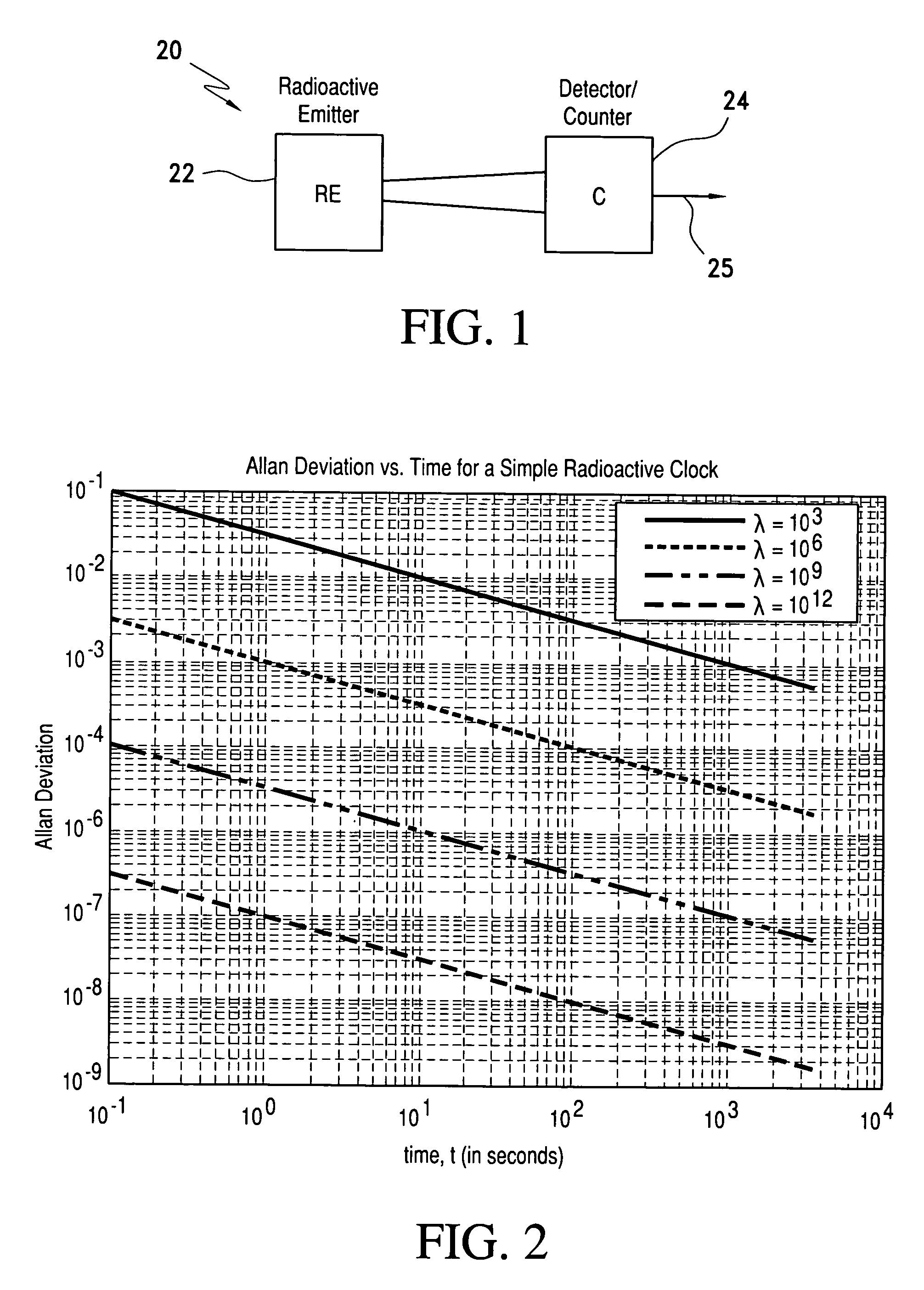
[0046] Turning now to a more detailed description of the invention, a radioactive decay based reference signal source 20 is illustrated in FIG. 1 as incorporating a radioactive emitter 22 and a detector, or counter, 24. The emitter 22 preferably is a radioactive beta emitter isotope, such as a thin film of Ni63, which decays to emit particles periodically at a rate corresponding to the material's disintegration rate. Radioactive emission detector 24 responds to the emitted particles to generate a corresponding periodic detection signal at its output 25. As is well known, such a detector may consist of a photodetector which responds to each emitted beta particle to produce an output signal, and in accordance with the present invention, this radioactive source serves as the basis for a stable time or frequency reference signal source which may function as an accurate, stable clock which has numerous advantages over known atomic clocks.

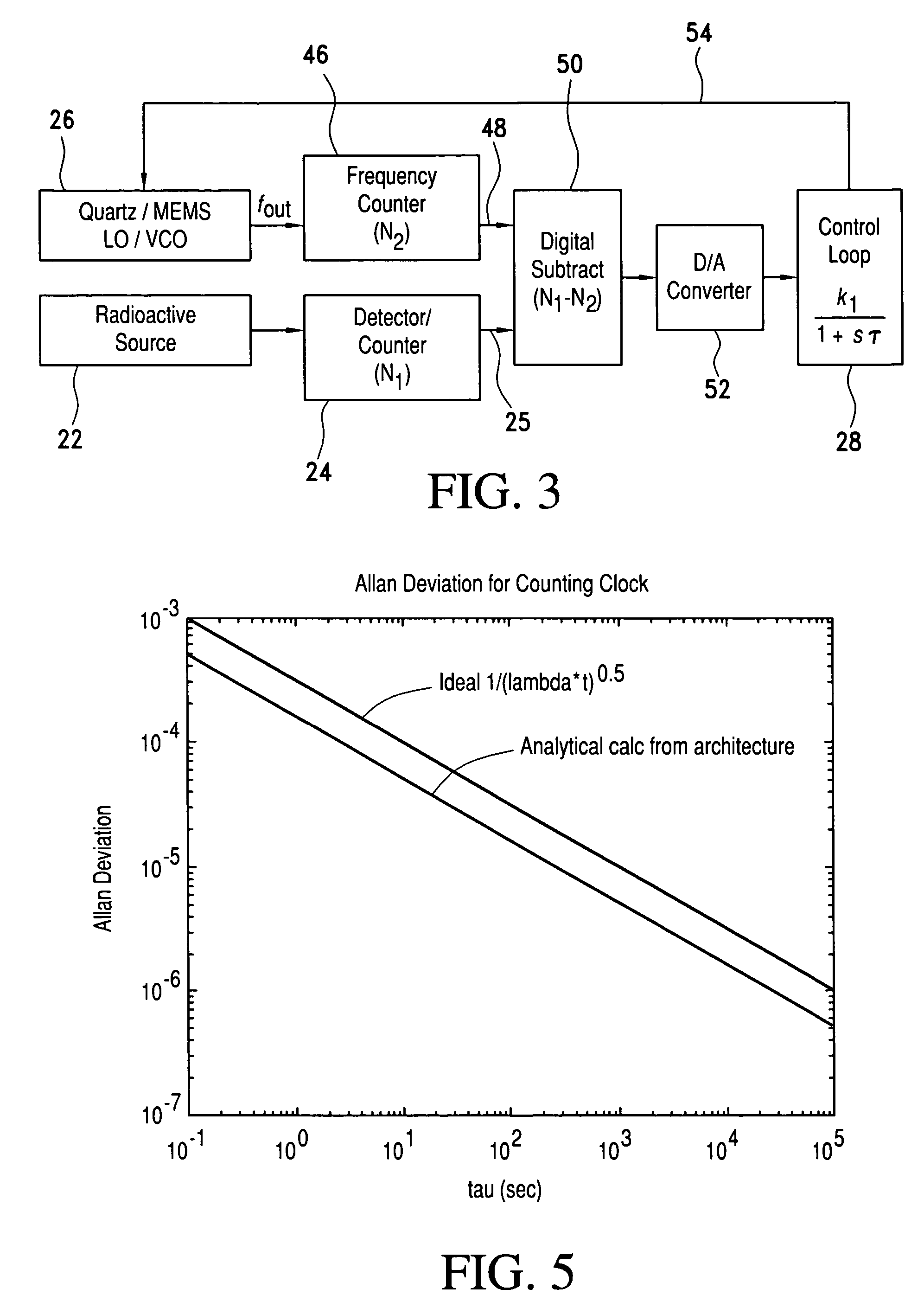
[0047] A simple counting clock architecture const...


PUM


Abstract

A signal source for use as a frequency source or time keeping signal source includes a radioactive emission source generating a substantially periodic signal corresponding to a radioactive material's disintegration rate. A radioactive emission detector generates a radioactive emission detection signal and, to stabilize the detected periodic signal, a dead time controlling attenuator blanks or shuts off the radioactive emission detection signal for a selected dead time interval in response to each detected radioactive emission (i.e., a detected signal pulse or signal component) generated by the source. The dead time controlling attenuator output provides a long-term and short-term a stable periodic signal.

Description

BACKGROUND OF THE INVENTION [0001] This application is a continuation of and claims priority to the filing date of U.S. provisional application Ser. No. 60 / 679,979, filed May 12th, 2005, the entire disclosure of which is hereby incorporated herein by reference.FIELD OF THE INVENTION [0002] The present invention relates in general, to a system and method for precise and stable time keeping and, more particularly to a signal source utilizing a radioactive decay rate as its reference. DISCUSSION OF THE PRIOR ART [0003] The need for more and more precise and stable time-keeping for a wide variety of applications has been on the rise, particularly in applications such as digital communications (such as for cell phone base stations, point-to-point communication, internet security, etc), global positioning systems (GPS) and, more critically, for security and identification applications such as friend-or-foe (IFF) communications. [0004] There are a wide variety of potential applications for...

Claims


Application Information

Patent Timeline
Patent Type & Authority Applications(United States)
IPC IPC(8): G01T1/20G01T1/24
CPCG04F5/16G01T1/171
Inventor LAL, AMITARADHAKRISHNAN, SHANKARLI, HUIGUO, HANG
Owner CORNELL RES FOUNDATION INC
Why Eureka
Try Eureka