High temperature direct coal fuel cell

a fuel cell and high temperature technology, applied in the field of high temperature fuel cells, can solve the problems of low conversion efficiency, limited capacity of other energy sources such as wind, solar energy, geothermal energy, nuclear energy, etc., and achieve the effect of increasing the cost of cosub, and increasing the cost of co-sub

Active Publication Date: 2006-11-16
TURGUT GUR
View PDF18 Cites 39 Cited by
  • Summary
  • Abstract
  • Description
  • Claims
  • Application Information

AI Technical Summary

Problems solved by technology

Other energy sources such as wind, solar, geothermal, and nuclear offer limited capacity only.
Conversion of the chemical energy of coal to electricity ordinarily requires multiple processing steps that suffer from Camot constraints and ultimately results in low conversion efficiencies.
However, these are relatively new and expensive technologies with capital costs in excess of $1700 / kW without CO2 capture and more than $2200 / kW with CO2 capture [N. Holt, GCEP Advanced Coal Workshop, Provo, Utah, Mar. 15, 16 (2005)].
The quest for direct carbon conversion to electricity is not new, however, and has been pursued in waves of activity for over 150 years.
However, his results were not encouraging because of the direct chemical oxidation of carbon by the potassium nitrate electrolyte.
Unfortunately, Jacques did not give reliable information about cell characteristics and life of his battery.
Furthermore, at these high operating temperatures, it is thermodynamically possible to carry out only partial oxidation of carbon, which would hence reduce the efficiency of the fuel cell significantly.
The tetragonal-to-monoclinic phase transition is accompanied by a large molar volume (about 4%), which makes the practical use of pure zirconia impossible for high temperature refractory applications.

Method used


Image

  • High temperature direct coal fuel cell
  • High temperature direct coal fuel cell
  • High temperature direct coal fuel cell

Examples


Embodiment Construction

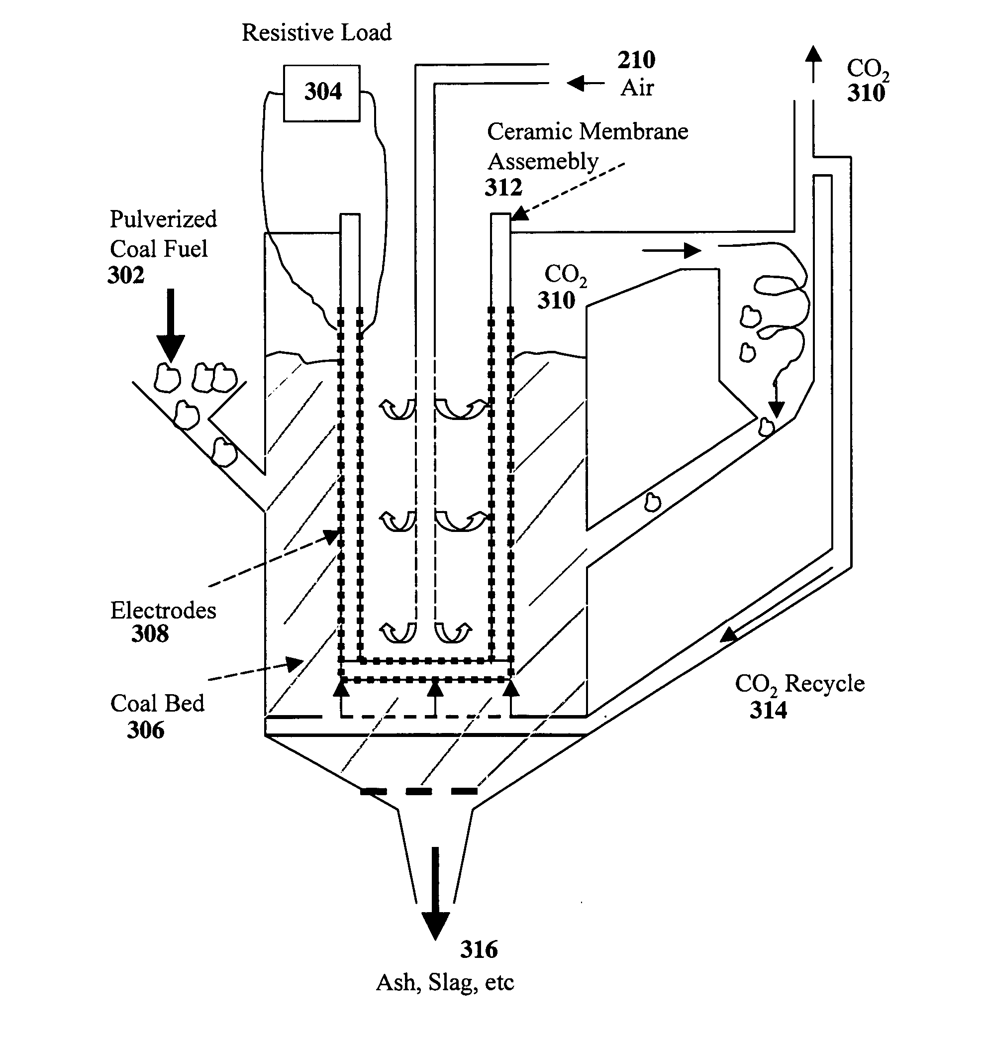
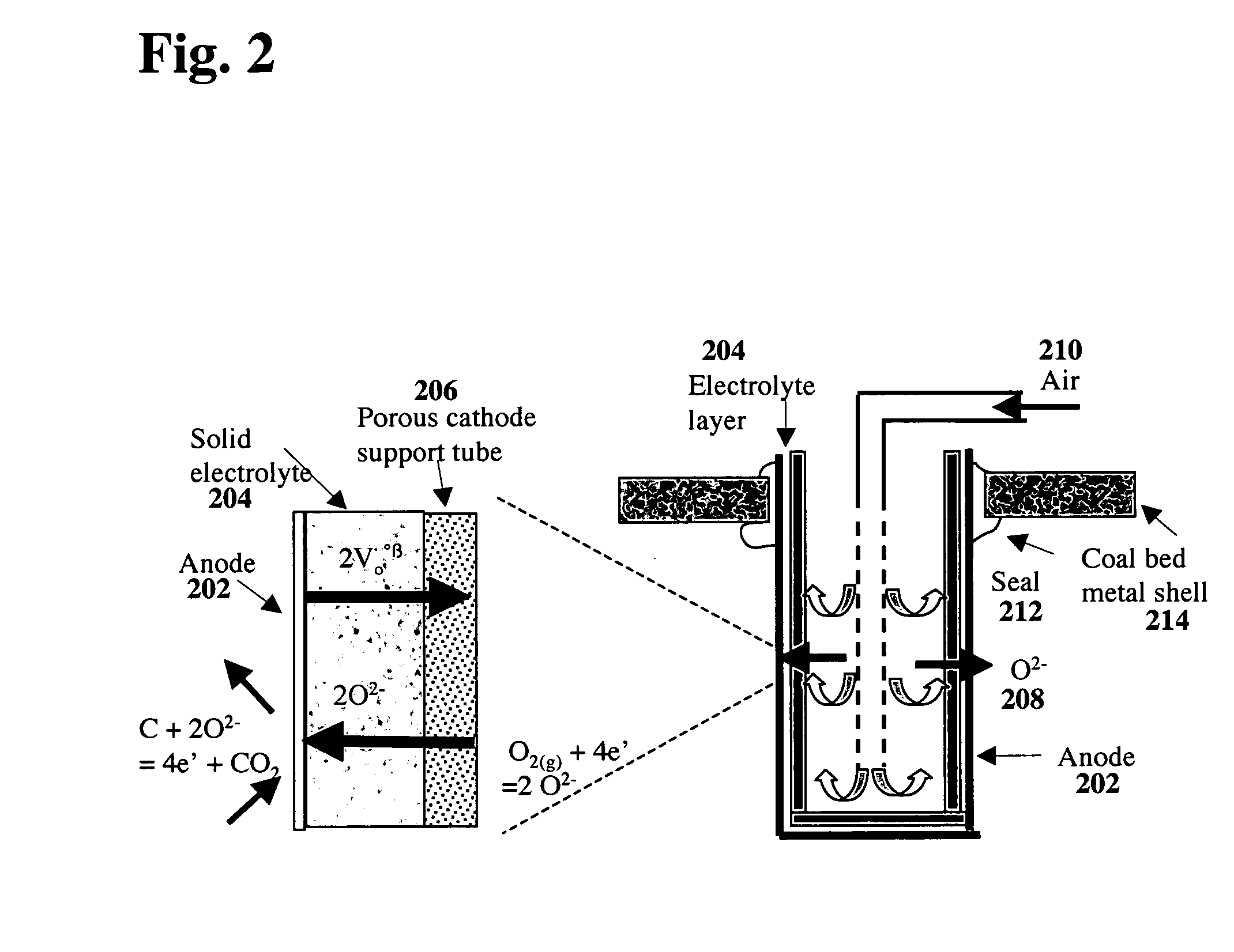
[0031] The electrochemical conversion of coal into electricity involves a high temperature fuel cell that features an oxide ion selective solid electrolyte that supplies the oxygen required for the electrochemical oxidation of carbon. Pulverized coal is introduced into the anode compartment of the cell with or without other solid constituents, such as sequestering agents for capturing the CO2 and SO2 produced.

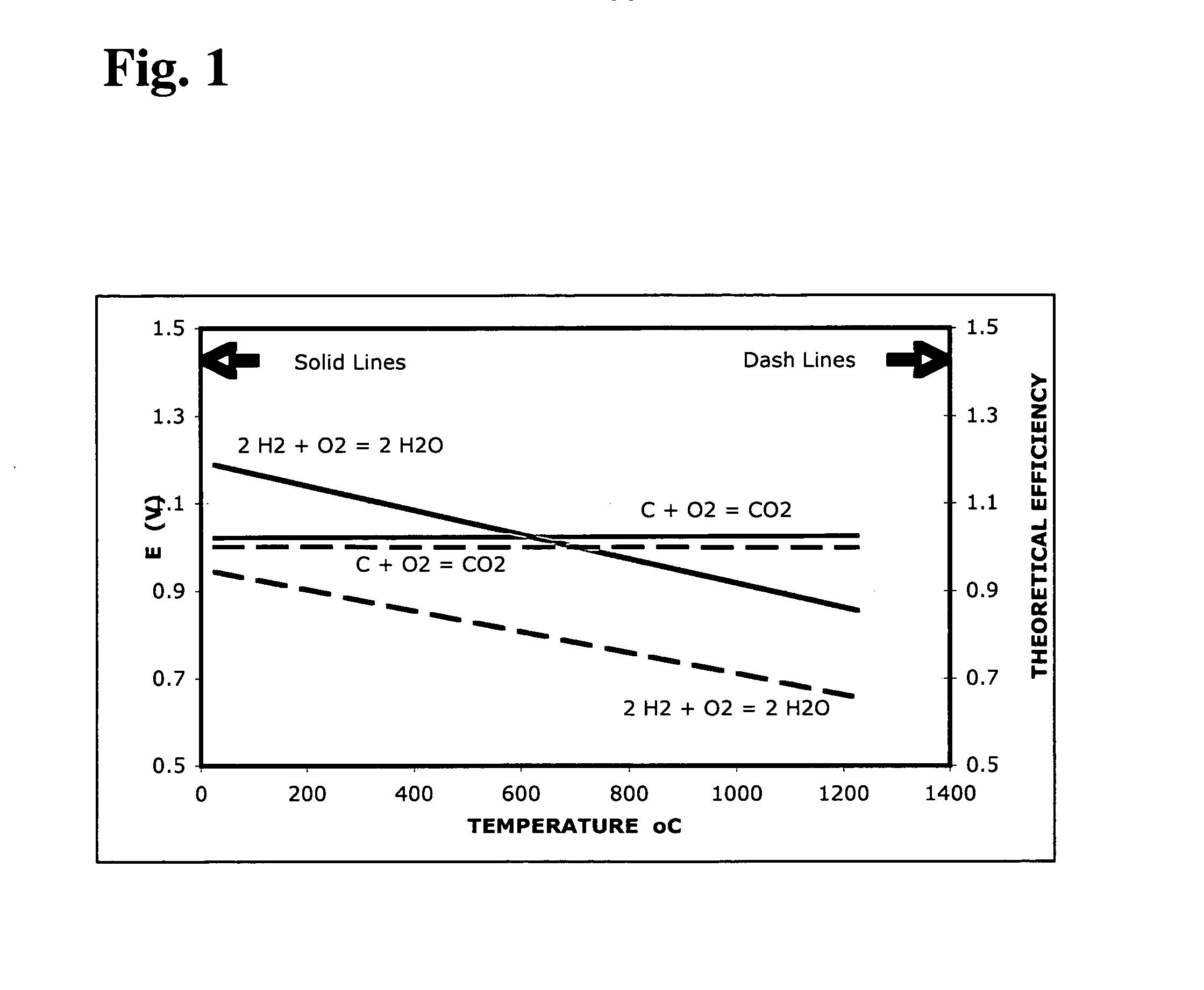
[0032]FIG. 1 shows the theoretical conversion efficiency and the expected open circuit voltage as a function of temperature for the electrochemical oxidation reaction of carbon. Note the temperature independence of E and efficiency for the carbon oxidation reaction, while the behavior is strongly dependent on temperature for the case of hydrogen.

[0033] Referring to Eq. (1), the open circuit voltage of the fuel cell is determined by the carbon-oxygen equilibrium at the anode, since the oxygen activity on the cathode side is fixed by air. FIG. 1 shows the theoretical conversion...


PUM

PropertyMeasurementUnit
operating temperatureaaaaaaaaaa

Abstract

The invention relates to direct conversion of coal into electricity in a high temperature electrochemical generator in a single step process. This novel concept promises nearly doubling the conversion efficiency of conventional coal-fired processes and offering near-zero emissions. The improved efficiency would mean that nearly half as much coal is mined and transported to the power plant, and half the greenhouse gases and other pollutants such as sulfur, mercury and dioxins are produced. It also offers several crucial distinctions from conventional coal-burning processes. Since the process does not involve the combustion of coal in air, it does not involve nitrogen and hence generates practically no NOx. Accordingly, there is also no latent heat lost to nitrogen. In this process, the oxygen necessary to oxidize coal is supplied through an ion selective ceramic membrane electrolyte. The resultant product stream primarily consists of CO2 and, hence, it is easier and cheaper to capture and sequester, compared to waste streams from conventional combustion processes where CO2 ordinarily constitutes about 15-20% of the flue stream, in which case it may first be separated from other constituents before sequestration.

Description

RELATED APPLICATIONS [0001] This application claims priority under 35 U.S.C. § 19(e) to provisional application No. 60 / 681,920 filed on May 16, 2005 titled “High Temperature Direct Coal Fuel Cell.”FIELD OF THE INVENTION [0002] This invention relates to the field of fuel cells, and in particular to the field of high temperature fuel cells for the direct electrochemical conversion of carbon-containing materials (such as coal) to electrical energy. This invention is further directed to fuel cells employing a single temperature zone. This invention is further directed to fuels cells wherein therein is direct physical contact of the anode surface with carbon particles. BACKGROUND OF THE INVENTION [0003] Coal is the most abundant and inexpensive energy source on our planet with sufficient reserves to meet a large fraction of the world's energy needs for many decades, even centuries to come. Other energy sources such as wind, solar, geothermal, and nuclear offer limited capacity only. As d...

Claims


Application Information

Patent Timeline
Patent Type & Authority Applications(United States)
IPC IPC(8): H01M12/00H01M8/12
CPCH01M8/0643H01M8/0662Y02E60/525H01M8/243Y02E60/521H01M8/1233Y02E60/50
Inventor GUR, TURGUT M.
Owner TURGUT GUR
Why Eureka
Try Eureka