Photoresist polymer compositions

a polymer composition and resist film technology, applied in the field of microfabrication, can solve the problems of increased irradiation dose in the upper portion of the resist film and decreased irradiation dose in the lower portion

Active Publication Date: 2006-11-16
FREESLATE +1
View PDF44 Cites 83 Cited by
  • Summary
  • Abstract
  • Description
  • Claims
  • Application Information

AI Technical Summary

Benefits of technology

[0012] Therefore, a need exists for polymeric resins which overcome one or more ...

Problems solved by technology

However, it is very difficult to perform microfabrication with a line width of sub-quarter micron using near ultraviolet rays.
However, phenol resins are not adequate to be used in ArF photoresists due to their strong absorption of ArF laser rays by aromatic rings, such that a sufficient amount of ArF laser rays does not effectively reach a lower portion of the resist film so that the irradiation dose is increased in the upper portion of the resist film and decreased in the lower portion.
Sufficient resolution is generally not obtained.
If the resist pattern after development is in the shape of a trapezoid, desired dimensional accuracy cannot be achieved in a succeeding step such as an etching step or ion implantation step.
Moreover, if the shape of the upper part of the resist pattern is not rectangular, the rate of removal o...

Method used


Image

  • Photoresist polymer compositions
  • Photoresist polymer compositions
  • Photoresist polymer compositions

Examples


examples

Polymer Synthesis

Procedure for the Living Polymerization of Methacrylate and Acrylate Monomers Encompassed by the Invention

[0233] The following is a general procedure for use with a CTA. (See Table I, column C) for the polymerization of monomers to form a polymer with the desired nominal compositions (Table I, column H) and targeted to have different molecular weights (Mw) at 100% conversion. The polymerization was conducted in an organic solvent, i.e., MEK (2-butanone) (which was degassed by three freeze-pump-thaw cycles) and the initiator MAIB (V601 from WAKO, 2,2′-dimethylazobis(methylpropionate)) was used to sustain the reaction. The stock solutions were made by weighing the monomers, CTA and initiator followed by cycling with vacuum into an oxygen free box where purified MEK was added.

[0234] Similar conditions can be used for other comonomer mixtures and with other CTAs. Target molecular weight is set as a molar ratio of the monomers to the CTA. The feed time can also be var...


PUM

PropertyMeasurementUnit
Volumeaaaaaaaaaa
Volumeaaaaaaaaaa
Volumeaaaaaaaaaa

Abstract

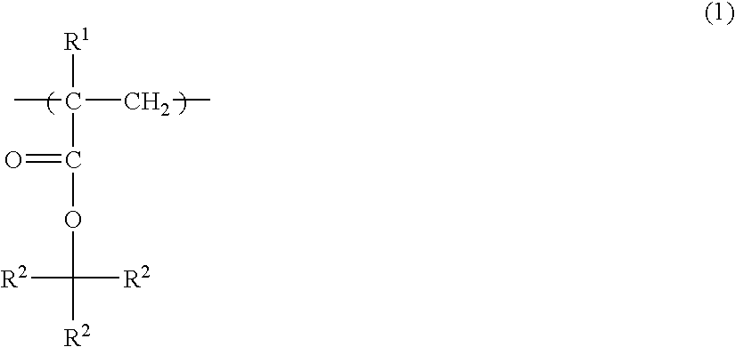
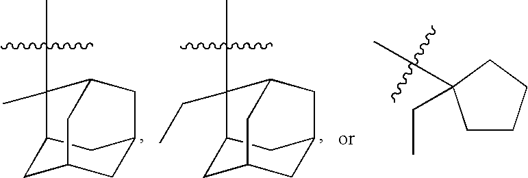
The present invention is directed to the preparation of photoresist polymers via living free radical polymerization techniques. Sterically bulky ester monomers are utilized as the polymerization components. Use of chain transfer agents is included in polymerization processing conditions. Cleavage of polymer terminal end groups that include a heteroatom are described.

Description

CROSS-REFERENCE TO RELATED APPLICATION [0001] This application is a continuation application of International Application No. PCT / US2004 / 020351, filed 25 Jun. 2004 and published as WO 2005 / 003198 A1 on 13 Jan. 2005, which claims priority to U.S. Provisional Patent Application Ser. No. 60 / 483,310 filed Jun. 26, 2003, and claims the priority thereof, the subject matter of which is hereby incorporated by reference in its entirety.BACKGROUND OF THE INVENTION [0002] In the field of microfabrication represented by the manufacture of integrated circuit devices, lithographic technology enabling microfabrication with a line width of 0.20 μm or less has been demanded in order to increase the degree of integration. [0003] A conventional lithographic process utilizes near ultraviolet rays such as an i-line radiation. However, it is very difficult to perform microfabrication with a line width of sub-quarter micron using near ultraviolet rays. [0004] Therefore, in order to enable microfabrication...

Claims


Application Information

Patent Timeline
IPC IPC(8): G03C1/00C08F20/18G03F7/039
CPCC08F20/18G03F7/0397C08F220/28C08F220/18C08F220/283C08F220/1812G03F7/039C08F220/281
Inventor BENOIT, DIDIERSAFIR, ADAMCHANG, HAN-TINGCHARMOT, DOMINIQUENISHIMURA, ISAOSOYANO, AKIMASAOKAMOTO, KENJIWANG, YONG
Owner FREESLATE
Why Eureka
Try Eureka