Insect repellent and attractant and auto-thermostatic membrane vapor control delivery system

Active Publication Date: 2006-11-23
ENERGY RELATED DEVICES
View PDF44 Cites 96 Cited by
  • Summary
  • Abstract
  • Description
  • Claims
  • Application Information

AI Technical Summary

Benefits of technology

[0011] An expected mosquito targeting sequence is to initially activate when elevated carbon dioxide or chemical scents are detected, and to fly toward the concentration gradient plume of chemical traces. Periodic puffs of carbon dioxide and metabolic chemicals may further confirm the target is an animal rather than a plant. At closer range when the eyes or infrared sensors of the insect detect an eye or surface in the proper temperature range and emission, the mosquitos fly toward it. Some surfaces may be animal body temperatures but are not emitting a light spectrum of a wetted surface that is characteristic of the eye such as metal surfaces and non-living objects. Use the sound of other female mosquitoes flying near the prey at 500 Hertz to help locate the prey. As approach is made toward the eye, the mosquitos move toward the edges and in particular the contrast color perimeter area and the pink tissue.
[0034] The catalytic heater can be incorporated into a system for various applications. One of the unique features of using a liquid fuel with the selectively permeable membrane in proximity to the catalytic heater is that when the fuel reaches its boiling point it removes fuel by boiling away from the catalytic reaction site and subsequently limits the maximum temperature. The vaporized fuel can be condensed in a heat exchanger and can deliver the thermal output of the heater efficiently. This fuel boiling mechanism along with the back diffusion of carbon dioxide and nitrogen can also be used to keep the fuel homogenous and self purging. By keeping the fuel homogenous and not in direct contact with catalysts, the heater can easily be purged of fuel contamination by draining the fuel. Critical New Features Include, but are not Limited to, the Following:

Problems solved by technology

The center of the eye is unsuitable due to the lack of blood vessels and the rapid response of the eyelids should push the insects off the eye.

Method used


Image

  • Insect repellent and attractant and auto-thermostatic membrane vapor control delivery system
  • Insect repellent and attractant and auto-thermostatic membrane vapor control delivery system
  • Insect repellent and attractant and auto-thermostatic membrane vapor control delivery system

Examples


Embodiment Construction

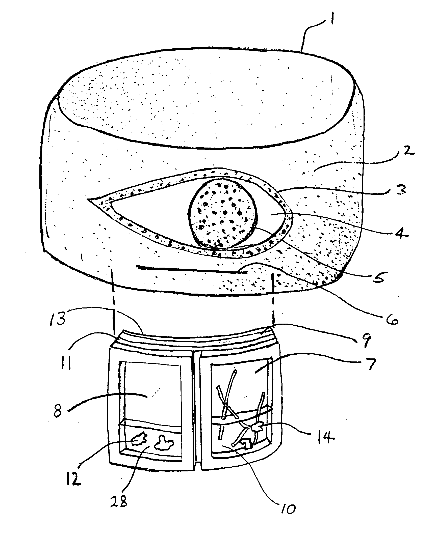
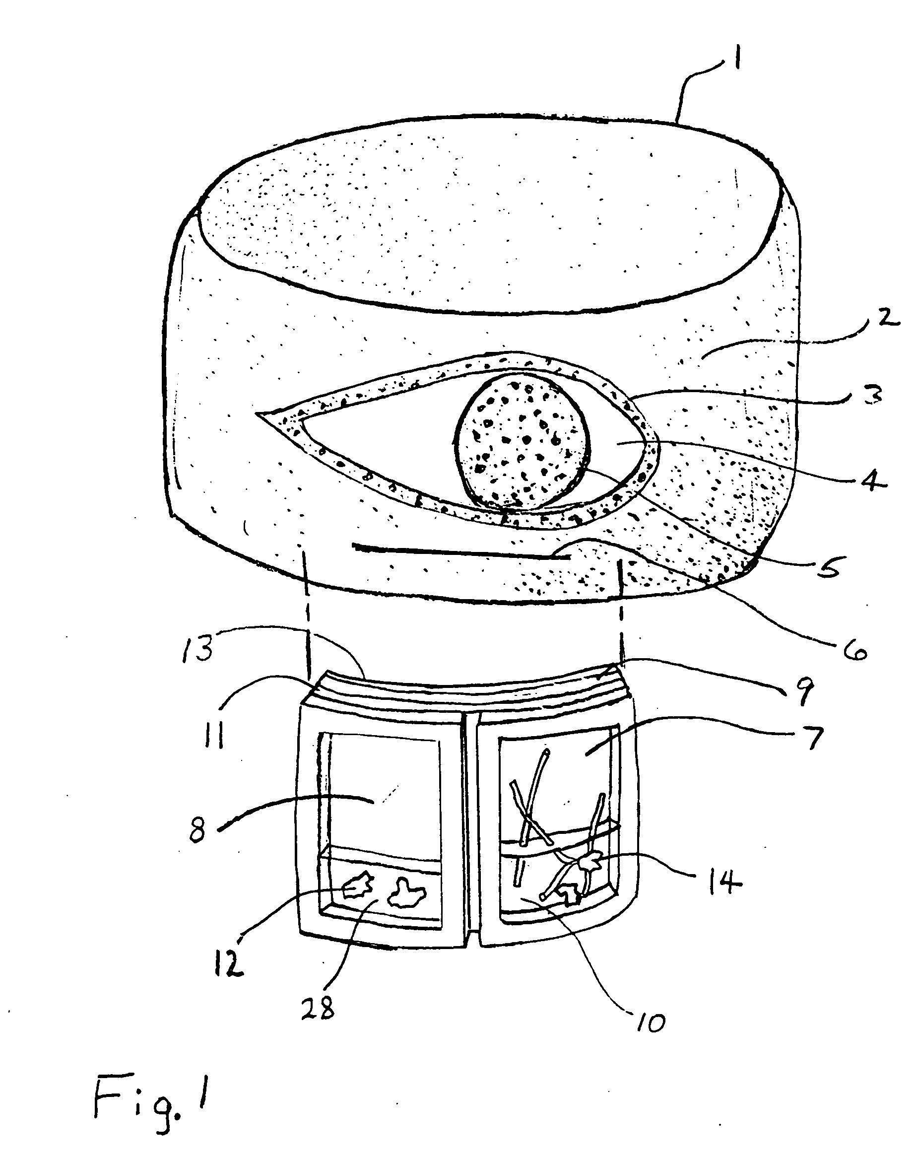
[0066] In FIG. 1 a view of the cloth wrist or ankle band 1 with the repellent ampoule 7 shown removed from the interior of the wristband 1. The band 1 is made with cotton, Cool Max® polyester fabric, silk, or an elastic weave Nylon fabric (texollini, 2575 El Presidio St., Long Beach, Calif. 90810). The band 1 is cut and sewn in the form of a circular tube with an interior volume (pocket) 6. The pocket 6 in the band can have sewn restrictions to contain the rubber ampoules 7, 8 just under the eye pattern 3. Access to the pocket is provided by a slit opening 6 which is shown on the outer surface of the band. The slit opening 6 can also be placed on the interior of the band 1.

[0067] An eye like pattern is inked on the band 3, 4, 5. Features of the eye are a dark central area 5 colored black simulating a pupil. It may also be effective to simply have a round hole viewing the underlying ampoule being colored black. The pocket can also be lined or made with a membrane or fabric that has ...


PUM


Abstract

A membrane enclosed fluid diffusion system for insect attractants and repellents, auto thermostatic heaters, and chemical delivery using an additive and / or selectively permeable membrane that interacts with the enclosed fluid to maintain steady delivery rates over a range of temperature and humidity. Systems can be formed with permeable membranes, impermeable membranes, chemical hydrates, wicks, scent fluids, fuel fluids, catalytic heaters, energy conversion devices, visible images, infrared images, trapping systems, sound systems, electronics, and apparel. The device results in efficient and effective devices for mosquito control drug delivery, and portable heaters.

Description

[0001] This application claims the benefit of U.S. Provisional Application No. 60 / 682,293, filed May 18, 2005, which is hereby incorporated by reference in its entirety.BACKGROUND OF THE INVENTION [0002] To attract, repel, or trap arthropods such as insects, mosquitoes, chiggers, flies, fleas, and ticks, systems typically take advantage of their specific behaviors of search, locate, or avoidance. Mosquitoes in particular have a sophisticated array of means and behavior to locate their prey and avoid hazards. [0003] Mosquitoes can detect distant carbon dioxide emissions and moisture. Over 50 chemicals, such as octanol, and lactic acid, have been identified as attractants to mosquitoes and presumably have been used as chemical signatures of their prey. Mosquitoes can detect the warm surfaces of their prey and can distinguish between cold and hot surfaces and avoid those that are not within typical body temperatures of their prey. They are attracted to contrasting and colored surfaces ...

Claims


Application Information

Patent Timeline
IPC IPC(8): A01M1/20A01M29/10A01M29/12
CPCA01M1/02A01M1/023A01M1/06A01M1/08A01M29/12A01M1/2061A01M1/2088A01M1/223A01M29/10A01M1/2044
Inventor HOCKADAY, ROBERT G.
Owner ENERGY RELATED DEVICES
Why Eureka
Try Eureka