Organic light emitting display apparatus
a light-emitting display and organic technology, applied in the direction of organic semiconductor devices, thermoelectric devices, solid-state devices, etc., can solve the problems of oxidizing the layer itself, limiting the aperture ratio, and reducing the light-emitting voltag
- Summary
- Abstract
- Description
- Claims
- Application Information
AI Technical Summary
Benefits of technology
Problems solved by technology
Method used
Image
Examples
example 1
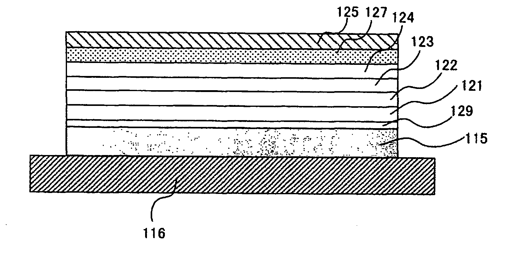
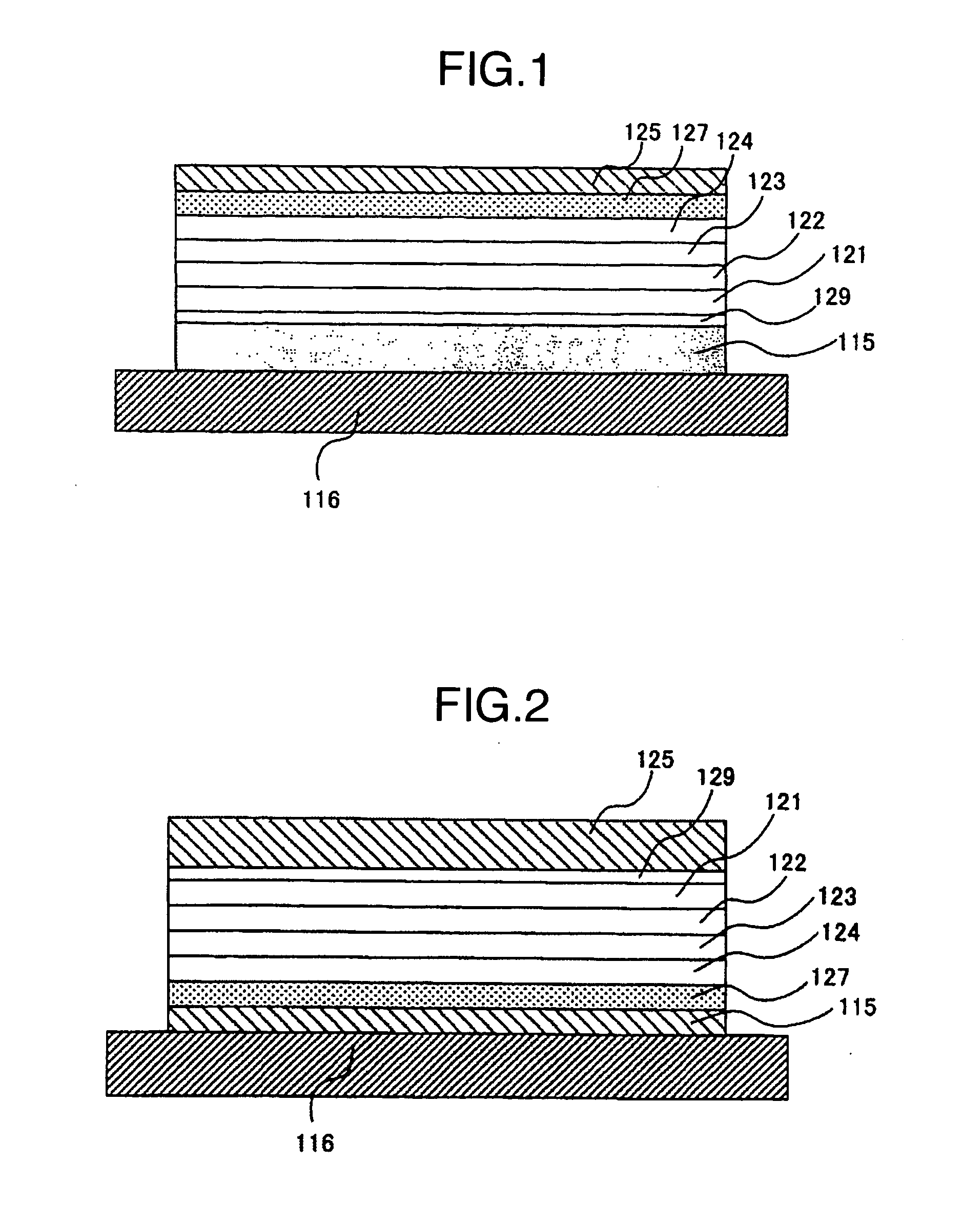
[0061] An example of organic light emitting display apparatus according to the present invention is explained below. FIG. 1 is a cross-sectional view of the organic light emitting display apparatus according to Example 1 of the present invention. The lower electrode 115 comprises an Cr film formed by EB deposition. The electrode film was patterned by using a shadow mask, and its thickness was 100 nm.
[0062] Then a 50 nm thick co-deposition film of F4-TCNQ and copper phthalocyanine was formed by two-source simultaneous vacuum deposition using a shadow mask for patterning. The F4-TCNQ:copper phthalocyanine molar ratio was 1:1. This co-deposition film functions as a hole injection layer 129.
[0063] Then a film of 4,4-bis[N-(1-naphthyl)-N-phenylamino]biphenyl (hereinafter abbreviated as α-NPD) with a thickness of 50 nm was formed by vacuum deposition using a shadow mask for patterning. The deposition region was 1.2 times each edge of the lower electrode. This α-NPD film works as a hole ...
example 2
[0071] Another example of organic light emitting display apparatus of the present invention is explained below.
[0072] An organic light emitting display apparatus same as Example 1 in structure but different in thickness of the buffer layer was fabricated.
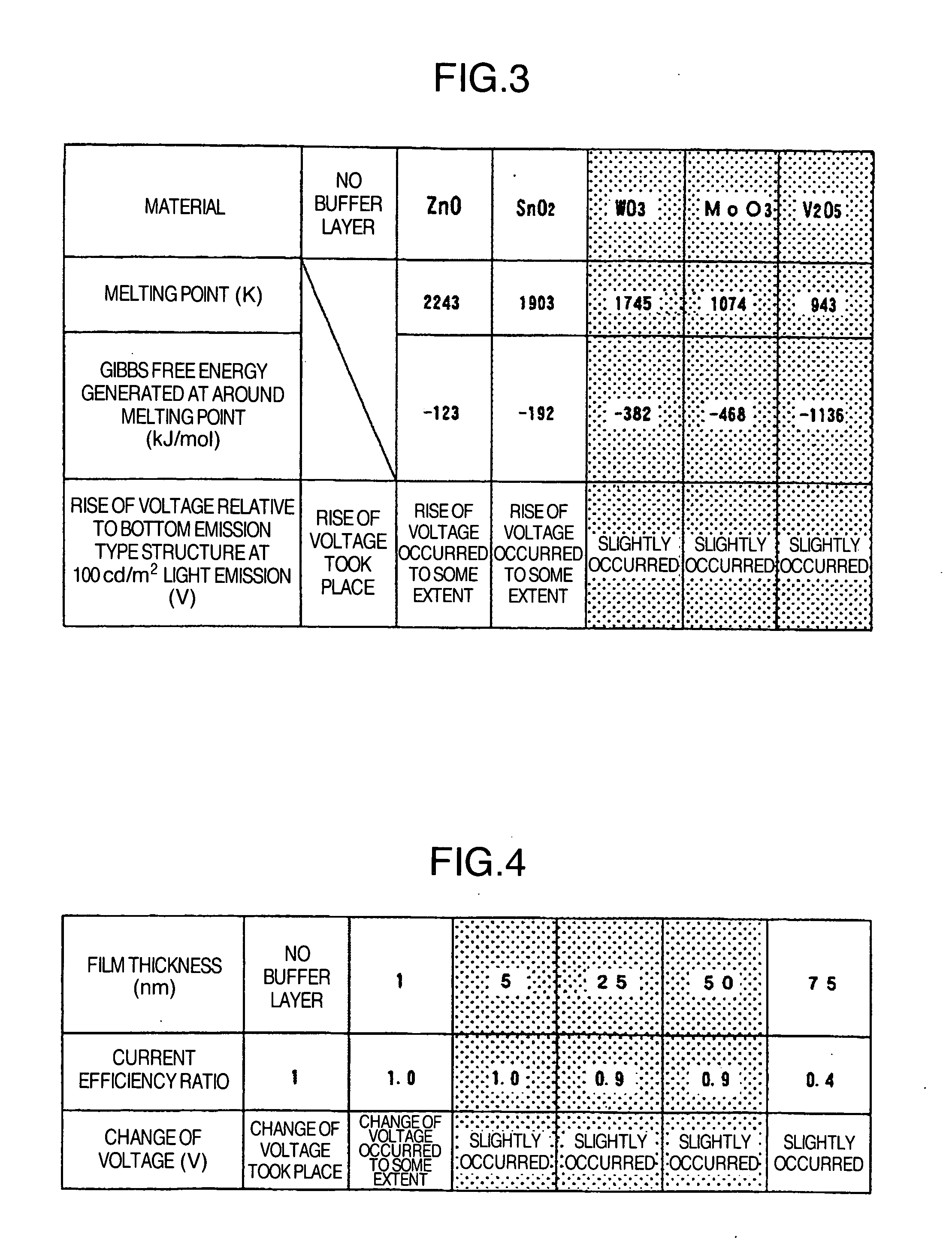
[0073] A film of vanadium oxide was formed as buffer layer 127 by EB deposition using a shadow mask for patterning. The film thickness was 1, 5, 25, 50 and 75 nm. A similar display apparatus having no buffer layer was also made by way of comparison. The vanadium oxide film had a composition of V:O=1:2.45.
[0074]FIG. 4 shows the change of voltage and current efficiency ratio according to the buffer layer thickness at 100 cd / m2 light emission. The change of voltage shown here is the one relative to the bottom emission type display apparatus shown in FIG. 2. Current efficiency ratio is the ratio to the current efficiency of the bottom emission type display apparatus which is supposed to be 1. If the buffer layer thickness is less tha...
example 3
[0075] Still another example of the organic light emitting display apparatus according to the present invention will be explained. FIG. 5 is a cross-sectional view of the organic light emitting display apparatus in the instant example of the present invention.
[0076] A 150 nm thick Al—Si film was formed by sputtering as reflection electrode 200 and patterned by photolithography. Also, an ITO film, 90 nm thick, was formed by sputtering as lower electrode 115 and patterned by photolithography.
[0077] Then polyethylenedioxythiophene (PEDT) incorporated with polystyrenesulfonic acid (PSS) was spin coated thereon to form a film having a thickness of 40 nm after dried at 200° C. This PSS-incorporated PEDT film functions as a hole injection layer 129.
[0078] On this film was further spin coated polyfluorene to form a 40 nm thick film after dried at 80° C. This polyfluorene film serves as a light emitting layer 122.
[0079] On this polyfluorene film was formed an Alq film, 10 nm thick, by va...
PUM
 Abstract
Description
Claims
Application Information
 - R&D
- Intellectual Property
- Life Sciences
- Materials
- Tech Scout
- Unparalleled Data Quality
- Higher Quality Content
- 60% Fewer Hallucinations
Browse by: Latest US Patents, China's latest patents, Technical Efficacy Thesaurus, Application Domain, Technology Topic, Popular Technical Reports.
© 2025 PatSnap. All rights reserved.Legal|Privacy policy|Modern Slavery Act Transparency Statement|Sitemap|About US| Contact US: help@patsnap.com


