Devices, systems and methods for retracting, lifting, compressing, supporting or repositioning tissues or anatomical structures
- Summary
- Abstract
- Description
- Claims
- Application Information
AI Technical Summary
Benefits of technology
Problems solved by technology
Method used
Image
Examples
first embodiment
[0171] In one embodiment of a method of manufacturing distal anchor 12, a tube is laser cut with a radially aligned laser. The geometry of the laser cut pattern is specified using a flat pattern drawing which is mapped onto the outside circumference of the tube. FIG. 2B shows a flat pattern that can be used to manufacture a distal anchor 12 of FIG. 2A. In FIG. 2B, flat pattern 36 comprises a rectangular region. The length of the rectangular region represents the length of the tube. The width of the rectangular region OC represents the outer circumference of the tube. In one embodiment, the length of the rectangular region is 0.315±0.005 inches and the width of the rectangular region is 0.088±0.001 inches. Flat pattern 36 further comprises a U-shaped slot 38 cut at the proximal end of flat pattern 36 as shown in FIG. 2B. The width of slot 38 is 0404±0.002 inches. The length of the straight region of slot 38 is 0.174±0.005 inches. The distal end of slot 38 comprises a semi-circular re...
second embodiment
[0172]FIG. 2C shows a flat pattern that can be used to design distal anchor 12 of FIG. 2A. In FIG. 2C, flat pattern 42 comprises a rectangular region. In one embodiment, the length of the rectangular region is 0.354±0.005 inches and the width of the rectangular region OC is 0.88±0.001 inches. Flat pattern 42 further comprises a W-shaped slot 44 cut at the proximal end of flat pattern 42 as shown in FIG. 2C. The distal end of slot 44 comprises two semi-circular regions as shown in FIG. 2C. In the embodiment shown in FIG. 2C, the radius of the semicircular regions is approximately 0.0015 inches. The length of slot 44 measured along the length of flat pattern 42 from the proximal end of flat pattern 42 to the proximal edges of the semicircular regions is 0.174±0.005 inches. Slot 44 encloses a central folding tab 46. In the embodiment shown in FIG. 2C, folding tab 46 comprises a straight proximal region and a tapering distal region. The length of the straight proximal region of folding ...
third embodiment
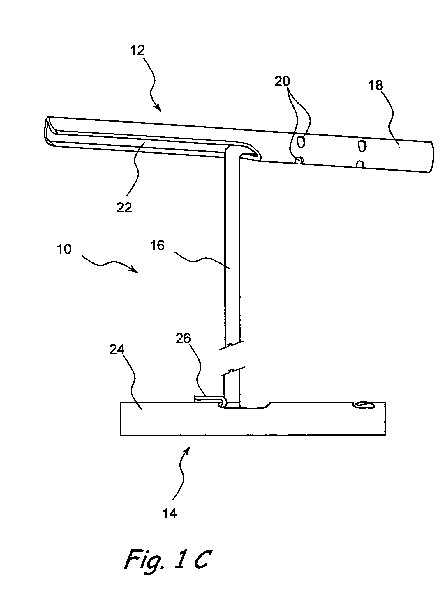
[0200] Connector 16 may enter or exit proximal anchor 14 through one or more connector openings. The walls of such openings may comprise one or more bent tabs. Such bent tabs may be bent inwards into the proximal anchor and may be used to wedge lock pin 104 to connector 16. For example, FIGS. 4F and 4G show longitudinal sections through a proximal anchor showing the steps of an embodiment of a method of attaching the proximal anchor to a connector. In the embodiment shown in FIG. 4F, proximal anchor 14 comprises a hollow tube. The hollow tube comprises a connector opening 100 located roughly midway between the ends of the tube. In the embodiment shown in FIG. 4F, connector opening 100 is made by cutting an H-shaped slot in the material of the tube. The H-shaped slot creates an outwardly opening flap 26. Outwardly opening flap 26 is folded as shown in FIG. 4F to create a blunt edge to connector opening 100. The H-shaped slot also creates an inwardly opening wedging tab 126 as shown i...
PUM
 Abstract
Description
Claims
Application Information
 - R&D
- Intellectual Property
- Life Sciences
- Materials
- Tech Scout
- Unparalleled Data Quality
- Higher Quality Content
- 60% Fewer Hallucinations
Browse by: Latest US Patents, China's latest patents, Technical Efficacy Thesaurus, Application Domain, Technology Topic, Popular Technical Reports.
© 2025 PatSnap. All rights reserved.Legal|Privacy policy|Modern Slavery Act Transparency Statement|Sitemap|About US| Contact US: help@patsnap.com


